Instrument Panel (IP) - Tie Bar / Cross Vehicle Beam
Instrument Panel Tie Bar Replacement
Removal Procedure
Caution: Refer to SIR Caution in Cautions and Notices.
1. Remove the instrument panel (IP) trim pad. Refer to Instrument Panel Trim Pad Replacement (Instrument Panel (IP) - Trim Pad Replacement).
2. Remove the brake pedal bracket and the reinforcement. Refer to Brake Pedal Assembly Replacement .
3. Reroute the transmission shift cable through the cross vehicle beam. Refer to Range Selector Lever Cable Adjustment in Automatic Transmission.
4. Release the retaining clips from the IP wiring harness and reposition the wiring harness out of the way.
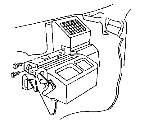
5. Remove the bolts retaining the HVAC module to the cross vehicle beam.
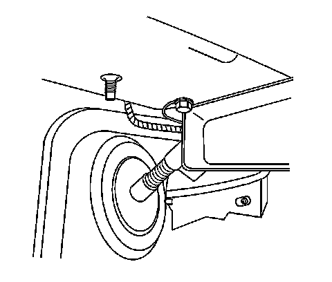
6. Remove the left cross vehicle ground wire.
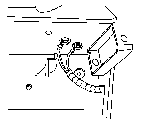
7. Remove the right cross vehicle ground wires.
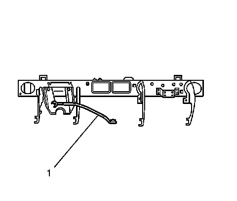
8. Unbolt the cross vehicle anchor tether (1) and let the tether hang.
9. Unclip the antenna cable from the cross vehicle beam.
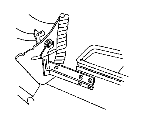
10. Remove the HVAC bracket from the cross vehicle beam bracket.
11. Remove the heads up display (HUD) bracket, if equipped.
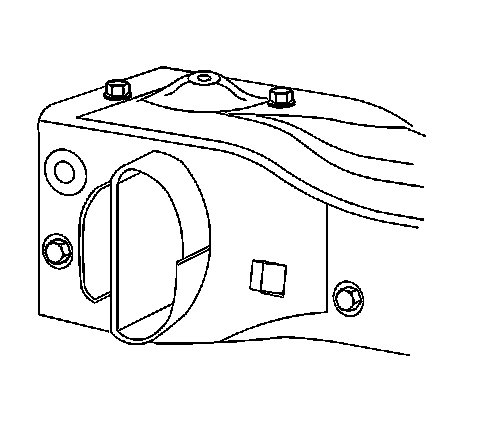
12. Remove the bolts retaining the cross vehicle beam to the left hinge pillar.
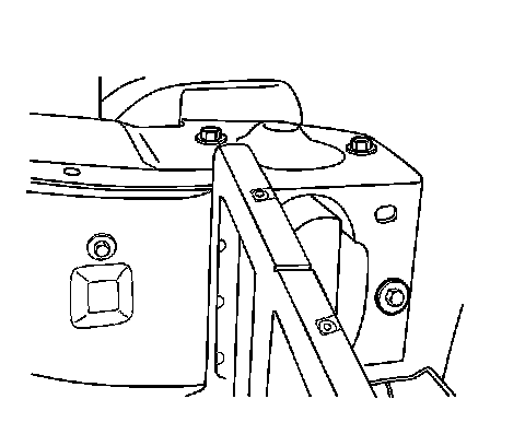
13. Remove the bolts retaining the cross vehicle beam to the right hinge pillar.
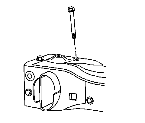
14. If you cannot remove the inner bolt because of interference with the windshield, gently bend the bolt stem when you remove the bolt from the cross vehicle beam. DISCARD the bolt.
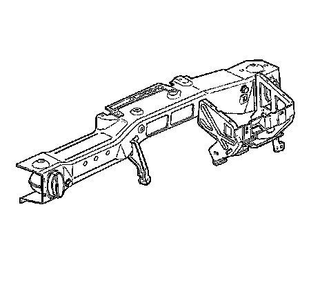
15. Remove the cross vehicle beam from the vehicle through the main wire harness.
16. Remove the front defroster duct.
Installation Procedure
1. Install the front defroster duct.
2. Install the cross vehicle beam to the vehicle through the main wire harness.
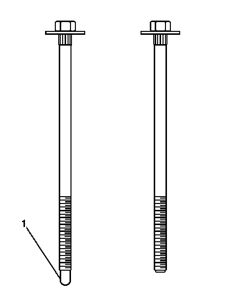
3. If you had to bend the cross vehicle beam bolt during removal, perform the following procedure:
1. Install a NEW bolt.
2. When reinstalling the instrument panel carrier with new bolt, You must shorten it 4-5 mm (3/16 in) by cutting off the guide feature (1) as shown.
3. if necessary, clean the threads prior to installation using a die.
4. When installed, 5-6 threads of the bolt should protrude through the fastener.
Important: Do NOT tighten the bolts.
4. Loosely install the bolts which secure the cross vehicle beam to the right hinge pillar.
5. Loosely install the bolts which secure the cross vehicle beam to the left hinge pillar.
Notice: Refer to Fastener Notice in Cautions and Notices.
6. Tighten all the bolts which secure the cross vehicle beam to the pillars.
Tighten the bolts to 25 Nm (18 lb ft).
7. Install the HVAC module to the cross vehicle beam with the retaining bolts.
Tighten the bolts to 10 Nm (89 lb in).
8. Install the bolts which retain the HVAC module to the center support bracket.
Tighten the bolts to 10 Nm (89 lb in).
9. Install the IP wiring harnesses into position and secure the retaining clips.
10. Install the cross vehicle anchor tether (1).
11. Clip the antenna cable to the cross vehicle beam.
12. Install the HVAC bracket to the cross vehicle beam bracket.
13. Install the HUD bracket, if equipped.
14. Install the brake pedal bracket and the reinforcement. Refer to Brake Pedal Assembly Replacement .
15. Install the IP trim pad. Refer to Instrument Panel Trim Pad Replacement (Instrument Panel (IP) - Trim Pad Replacement).
16. Install the front floor console. Refer to Front Floor Console Replacement (Front Floor Console Replacement).