B2532
CIRCUIT DESCRIPTIONThe BCM controls the operation of the fog lamps. When the park lamps are on, and the fog lamp switch is turned ON, the BCM grounds the control circuit of the fog lamp relay in order to illuminate the fog lamps.
CONDITIONS FOR RUNNING THE DTC
^ Voltage supplied to the module is in the normal operating range (approximately 9-16 volts).
^ The front fog lamp feature is enabled.
CONDITIONS FOR SETTING THE DTC
^ The BCM detects a short to ground or an open in the control circuit of the fog lamp relay when the fog lamps are not commanded ON.
^ The condition is present for longer than 3 ms.
ACTION TAKEN WHEN THE DTC SETS
The BCM stores DTC B2532 in memory.
CONDITIONS FOR CLEARING THE MIL/DTC
^ A current DTC B2532 clears when the BCM no longer detects an open or a short to ground in the control circuit of the fog lamp relay.
^ A history DTC B2532 clears after 100 consecutive ignition cycles.
^ A DTC B2532 will clear when commanded by a scan tool.
DIAGNOSTIC AIDS
^ If the DTC B2532 is a history DTC, the fault may be intermittent. Refer to Testing for Intermittent and Poor Connections in Diagrams.
^ An intermittent short to ground or an open in the following locations may cause an intermittent malfunction to occur:
- The control circuit of the fog lamps relay
- The fog lamps relay
- The Body Control Module (BCM)
TEST DESCRIPTION
Steps 1-13:
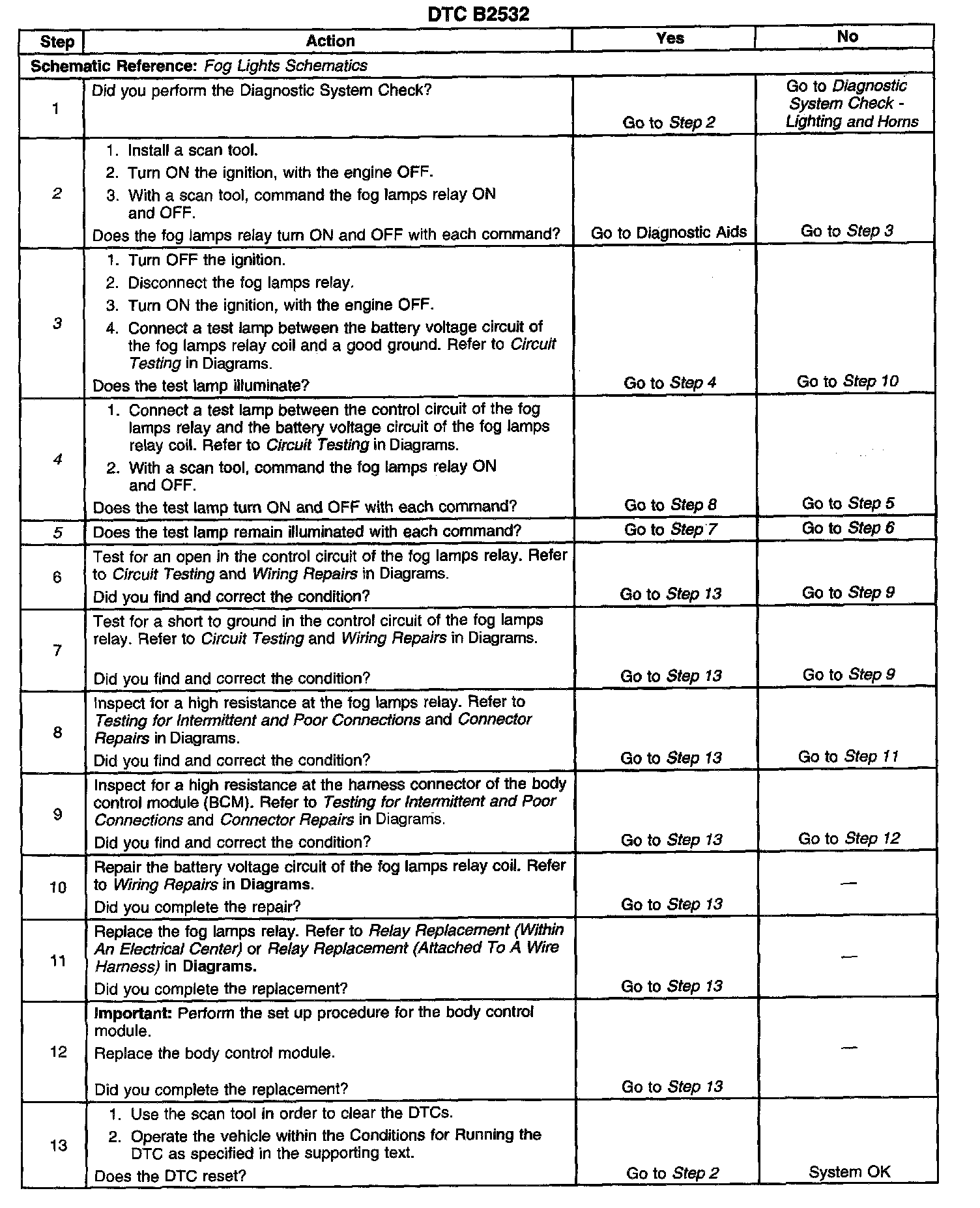
The number(s) below refer to the step number(s) on the diagnostic table.
2. Listen for an audible click when the fog lamps relay operates. Command both the ON and OFF states. Repeat the commands as necessary.
3. This step tests for voltage at the coil side of the fog lamps relay. The FOG LPS fuse supplies power to the coil side of the fog lamps relay.
4. This step verifies that the BCM is providing ground to the fog lamps relay.
5. This step tests whether ground is constantly being applied to the fog lamps relay.