B0078
CIRCUIT DESCRIPTIONSIR Schematics:
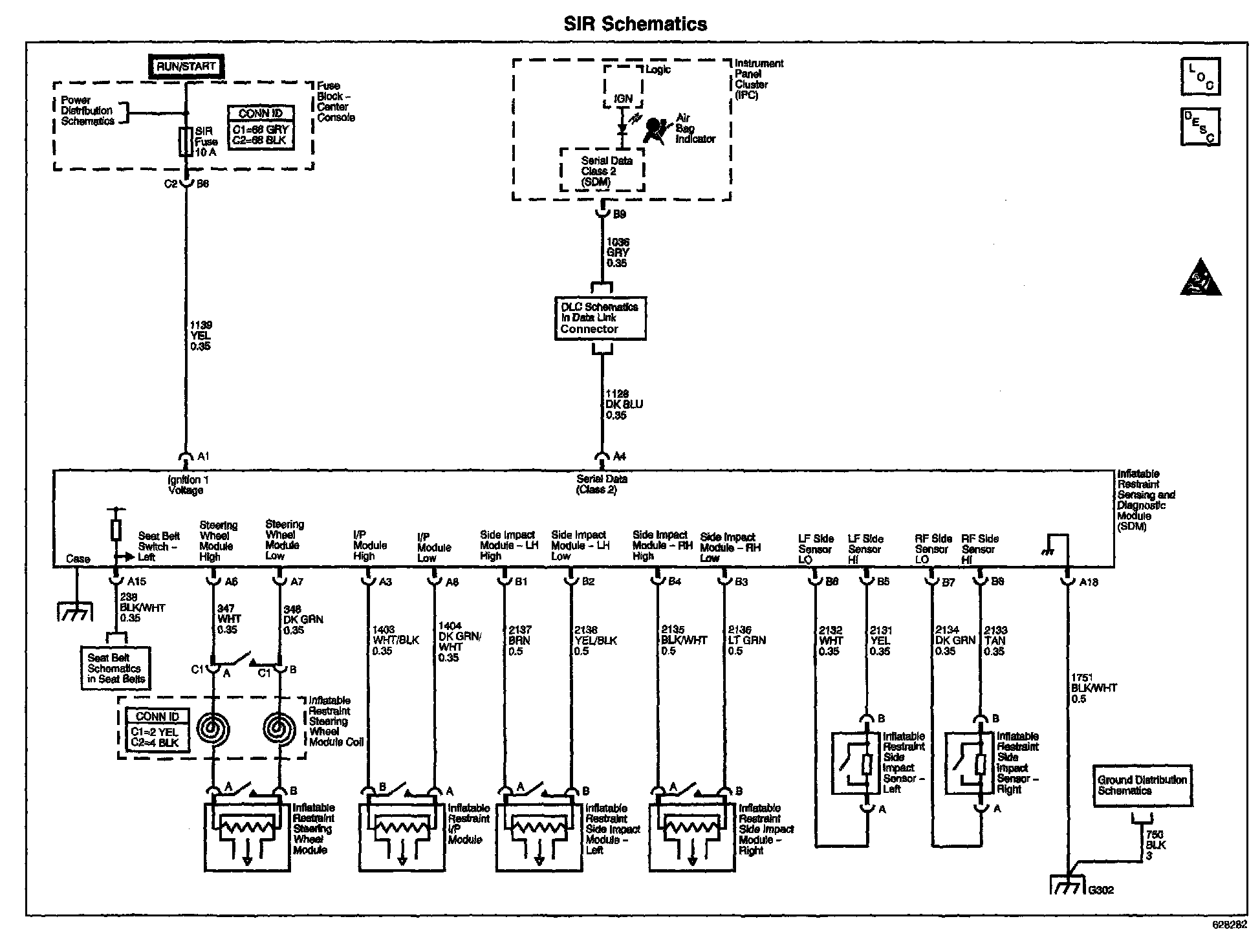
When the ignition is turned ON, the Inflatable Restraint Sensing And Diagnostic Module (SDM) performs tests to diagnose critical malfunctions within itself. Then, the SDM provides input power to the Inflatable Restraint Side Impact Sensor (SIS) - RF. When the input power is detected, the SIS responds by performing internal diagnostics. After that, the SIS sends an ID message to the SDM. The SDM will consider this to be a valid ID if the response time is less than 5 seconds after the SIS is powered up. The SIS will continually communicate a status message to the SDM. The SDM can reset the SIS by removing and applying power to it.
CONDITIONS FOR RUNNING THE DTC
Ignition 1 voltage is within the normal operating voltage range.
CONDITIONS FOR SETTING THE DTC
The DTC will set if one of the following conditions occur:
^ A valid ID message is not received by the SDM within 5 seconds of the SIS being powered up A valid ID message is not received
^ The SDM has failed twice to reset the SIS
ACTION TAKEN WHEN THE DTC SETS
^ The SDM commands the AIR BAG indicator ON via Class 2 serial data.
^ The SDM attempts to reset the SIS.
CONDITIONS FOR CLEARING THE DTC
^ The condition responsible for setting the DTC no longer exists and the scan tool Clear DTCs function is used.
^ A history DTC will clear once 255 malfunction free ignition cycles have occurred.
DIAGNOSTIC AIDS
Thoroughly inspect the wiring and connectors. An incomplete inspection of the wiring and the connectors may result in misdiagnosis, causing a part replacement with the reappearance of the malfunction.
The following are possible causes of the malfunction:
^ A short between the SIS - RF voltage circuit and the SIS - RF signal circuit
^ A short to ground, short to voltage, open, or high resistance in the SIS - RF voltage circuit or in the SIS - RF signal circuit
^ The SIS connector
^ An internal SIS malfunction
^ The SDM connector
^ An internal SDM malfunction
If an intermittent condition exists, refer to Testing for Intermittent and Poor Connections in Diagrams.
TEST DESCRIPTION
Steps 1-12:
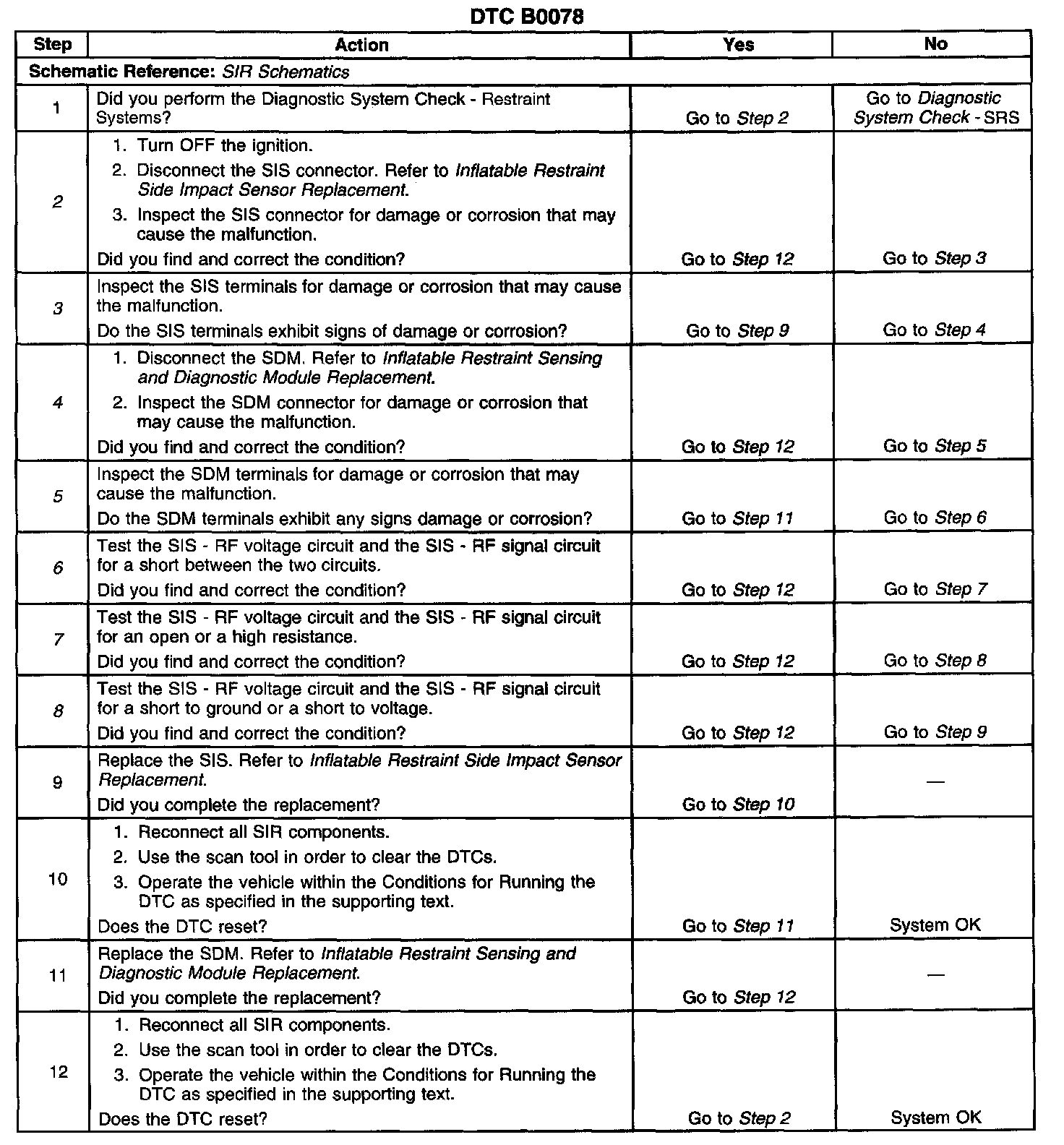
The numbers below refer to the step numbers on the diagnostic table:
2. Tests to see if the SIS connector is damaged or corroded
3. Tests to see if the SIS terminals are damaged or corroded
4. Tests to see if the SDM connector is damaged or corroded
5. Tests to see if the SDM terminals are damaged or corroded
6. Tests to see if there is a short between the SIS - RF voltage circuit and the SIS - RF signal circuit
7. Tests to see if there is an open or high resistance in the SIS - RF voltage circuit or in the SIS - RF signal circuit
8. Tests to see if there is a short to ground or a short to voltage in the SIS - RF voltage circuit or in the SIS - RF signal circuit