Test AK: Traction Off Indicator Always On: Testing
- If anti-lock brake diagnostic system check has been performed, go to next step. If anti-lock brake diagnostic system check has not been performed, go to ANTI-LOCK BRAKE DIAGNOSTIC SYSTEM CHECK under SELF-DIAGNOSTIC SYSTEM in BODY CONTROL MODULES - AZTEK article.
- Turn ignition switch to OFF position. Connect scan tool to Data Link Connector (DLC). DLC is located under left side of instrument panel. Turn ignition switch to RUN position. Using scan tool, observe TRACTION SWITCH parameter from Body Control Module (BCM) data list. If scan tool parameter displays OFF, go to next step. If scan tool parameter does not display OFF, go to step 4.
- Activate traction control switch. Using scan tool, observe TRACTION SWITCH parameter from BCM data list. If scan tool parameter does not change state, go to next step. If scan tool parameter changes state, concern may be intermittent. For aid in diagnosing intermittent problems, see PROBLEM DIAGNOSIS under INTERMITTENTS.
- Turn ignition switch to OFF position. Disconnect traction control switch 8-pin harness connector. Traction control switch is located in center console switchbank. Turn ignition switch to RUN position. Using scan tool, observe TRACTION SWITCH parameter from BCM data list. If scan tool parameter displays OFF, go to next step. If scan tool parameter does not display OFF, go to step 7.
- Check for short to ground in traction control switch signal circuit, Brown/White wire between gray BCM harness connector C0 terminal B7 and traction control switch harness connector "D". See Figure and Fig 1
. If no problem exists, go to next step. If problem exists, repair as necessary and go to step 10.
- Check for poor, loose or corroded terminals at BCM harness connectors. If problem exists, repair as necessary and go to step 10. If no problem exists, go to step 8.
- Check for poor, loose or corroded terminals at traction control switch harness connector. If problem exists, repair as necessary and go to step 10. If no problem exists, go to step 9.
- Replace BCM. See BODY CONTROL MODULE under REMOVAL & INSTALLATION in BODY CONTROL MODULES - AZTEK article. After repairs are made, go to step 10.
- Replace traction control switch. See appropriate ANTI-LOCK article in BRAKES. After repair are made, go to next step.
- Check system for normal operation. If system operates normally, test is complete. If system does not operate normally, go to step 2.
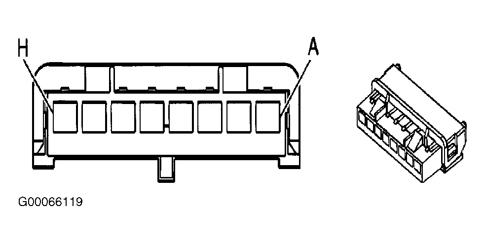 Courtesy of GENERAL MOTORS CORP.