Test M: Head Up Display Inoperative
- If head up display diagnostic system check has been performed, go to next step. If head up display diagnostic system check has not been performed, go to HEAD UP DISPLAY DIAGNOSTIC SYSTEM CHECK under SELF-DIAGNOSTIC SYSTEM.
- Turn ignition switch to RUN position. Adjust Head Up Display (HUD) dimmer switch to full intensity. If HUD display is not visible, go to next step. If HUD display is visible, concern may be intermittent. For aid in diagnosing intermittent problems, see PROBLEM DIAGNOSIS under INTERMITTENTS.
- Turn ignition switch to OFF position. Disconnect HUD module 12-pin harness connector. HUD module is located under trim panel on top of instrument panel. Turn ignition switch to RUN position. Check for open, short to ground or short to voltage in HUD module ignition circuit, Brown wire between Center Console (CC) fuse block harness connector C1 terminal B7 and HUD harness connector terminal "M". See Figure and Fig 1. If no problem exists, go to next step. If problem exists, repair as necessary and go to step 11.
- Using test light connected to battery voltage, probe HUD module harness connector "F" (White wire). Turn HUD dimmer switch to OFF position. If test light illuminates, go to next step. If test light does not illuminate, go to step 6.
- Disconnect HUD dimmer switch 6-pin harness connector. If test light is still illuminated, go to step 8. If test light is not illuminated, go to step 7.
- Check for poor, loose or corroded terminals at HUD harness connector. If problem exists, repair as necessary and go to step 11. If no problem exists, go to step 9.
- Check for poor, loose or corroded terminals at HUD dimmer switch harness connector. If problem exists, repair as necessary and go to step 11. If no problem exists, go to step 10.
- Repair short to ground in HUD dimmer signal circuit, White wire between HUD module harness connector "F" and HUD dimmer switch harness connector terminal No. 6. See Fig 1 and Fig 2
. After repairs are made, go to step 11.
- Replace HUD module. See HEAD UP DISPLAY MODULE under REMOVAL & INSTALLATION. After repairs are made, go to step 11.
- Replace HUD dimmer switch. See HEAD UP DISPLAY DIMMER SWITCH under REMOVAL & INSTALLATION. After repairs are made, go to next step.
- Check system for normal operation. If system operates normally, test is complete. If system does not operate normally, go to step 2.
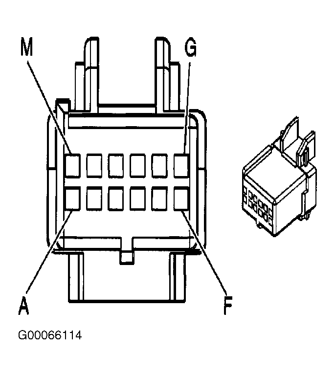 Courtesy of GENERAL MOTORS CORP.
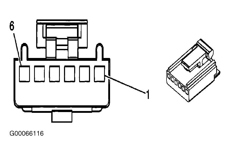 Courtesy of GENERAL MOTORS CORP.