Test Ac: Low Engine Oil Level Indicator Always On
- If instrument panel cluster diagnostic system check has been performed, go to next step. If instrument panel cluster diagnostic system check has not been performed, go to INSTRUMENT PANEL CLUSTER DIAGNOSTIC SYSTEM CHECK under SELF-DIAGNOSTIC SYSTEM.
- Turn ignition switch to OFF position. Connect scan tool to Data Link Connector (DLC). DLC is located under left side of instrument panel. Turn ignition switch to RUN position. Using scan tool, select Powertrain Control Module (PCM) data 2 list. If ENGINE OIL LEVEL parameter indicates OK, go to next step. If ENGINE OIL LEVEL parameter does not indicate OK, go to step 4.
- If low engine oil indicator is illuminated, go to step 10. If low engine oil indicator is not illuminated, concern may be intermittent. For aid in diagnosing intermittent problems, see PROBLEM DIAGNOSIS under INTERMITTENTS.
- Turn ignition switch to OFF position. Disconnect PCM 80-pin harness connector. PCM is located in engine compartment, inside air cleaner assembly. Turn ignition switch to RUN position. Using a test light connected to battery voltage, probe engine oil level indicator switch signal circuit, Brown wire between PCM harness connector C2 terminal No. 58 and engine oil level indicator switch harness connector terminal "A". See Figure and Fig 1
. If test light does not illuminate, go to next step. If test light illuminates, go to step 7.
- Check an open or for a short to voltage in engine oil level indicator switch signal circuit, Brown wire between PCM harness connector C2 terminal No. 58 and engine oil level indicator switch harness connector terminal "A". If no problem exists, go to next step. If problem exists, repair as necessary and go to step 12.
- Check for open in engine oil level indicator switch ground circuit, Black/White wire between ground and engine oil level indicator switch harness connector terminal "B". Ground point is located on bell housing left of starter, along with battery ground. If problem exists, repair as necessary and go to step 12. If no problem exists, go to step 8.
- Check for poor, loose or corroded terminals in PCM harness connector. If problem exists, repair as necessary and go to step 12. If no problem exists, go to step 9.
- Check for poor, loose or corroded terminals in engine oil level indicator switch harness connector. If problem exists, repair as necessary and go to step 12. If no problem exists, go to step 11
- Replace PCM. See POWERTRAIN CONTROL MODULE under REMOVAL & INSTALLATION in BODY CONTROL MODULES - AZTEK article. After repairs are made, go to step 12.
- Replace instrument panel cluster. See INSTRUMENT PANEL CLUSTER under REMOVAL & INSTALLATION. After repairs are made, go to step 12.
- Replace engine oil level indicator switch. After repairs are made, go to next step.
- Operate system to verify repair. If system operates normally, testing is complete. If system does not operate normally, go to step 2.
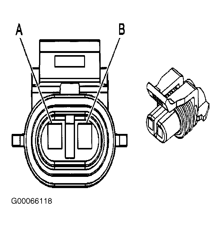 Courtesy of GENERAL MOTORS CORP.