Test S: Air Bag Indicator Circuit Malfunction: Testing
- If air bag system diagnostic system check has been performed, go to next step. If air bag system diagnostic system check has not been performed, see AIR BAG SYSTEM DIAGNOSTIC SYSTEM CHECK under SELF-DIAGNOSTIC SYSTEM in BODY CONTROL MODULES - AZTEK article.
- Cycle ignition switch from OFF, to RUN positions. Observe AIR BAG indicator when ignition switch is turned to RUN position. If AIR BAG indicator does not flash 7 times, go to next step. If AIR BAG indicator flashes 7 times, go to step 4.
- Replace Instrument Panel Cluster (IPC). See INSTRUMENT PANEL CLUSTER under REMOVAL & INSTALLATION. After repairs are made, go to step 13.
- Observe AIR BAG indicator after it has flashed seven times. If AIR BAG indicator does not turn Off after flashing seven times, go to next step. If AIR BAG indicator turns Off after flashing seven times, concern may be intermittent. For aid in diagnosing intermittent problems, see PROBLEM DIAGNOSIS under INTERMITTENTS.
- Turn ignition switch to OFF position. Connect scan tool to Data Link Connector (DLC). DLC is located under left side of instrument panel. Using scan tool, attempt to communicate with IPC. If scan tool communicates with IPC, go to next step. If scan tool does not communicate with IPC, go to SCAN TOOL DOES NOT COMMUNICATE WITH CLASS 2 DEVICE under SYSTEM TESTS in BODY CONTROL MODULES - AZTEK article.
- Using scan tool, observe SIR data list. If scan tool indicates ignition voltage is 9 volts or more, go to next step. If scan tool indicates that voltage is less than 9 volts, go to step 8.
- If scan tool indicates that voltage is 16 volts or more, perform engine electrical diagnostic systems check. See ENGINE ELECTRICAL DIAGNOSTIC SYSTEMS CHECK under SYSTEMS TESTS in BODY CONTROL MODULES - AZTEK article. If scan tool indicates that voltage is less than 16 volts, go to step 12.
- Disconnect SDM 34-pin harness connector. SDM is located under passenger front seat. Check for poor, loose or corroded terminals in SDM harness connector. If no problem exists, go to next step. If problem exists, repair as necessary and go to step 13.
- Remove Center Console (CC) fuse block SIR fuse (10-amp). CC fuse block is located behind right console access panel, inside of center console. Check for open or high resistance in ignition 1 voltage to SDM, Yellow wire between CC fuse block harness connector C2 terminal B6 and SDM harness connector terminal A1. See Figure and Fig 1
. See WIRING DIAGRAMS in appropriate AIR BAGS article. If no problem exists, go to next step. If problem exists, repair as necessary and go to step 13.
- Check for open or a high resistance in ignition 1 feed circuit, Yellow wire between CC fuse block harness connector C2 terminal B6 and SDM harness connector terminal A1. If no problem exists, go to next step. If problem exists, repair as necessary and go to step 13.
- Turn ignition switch to OFF position. Check for open or a high resistance in SDM ground circuit, Black/White wire between ground and SDM harness connector terminal A18. Ground point is located on right "B" pillar, under seat belt anchor. See Fig 1. If no problem exists, go to next step. If problem exists, repair as necessary and go to step 13.
- Replace SDM. See SENSING & DIAGNOSTIC MODULE under REMOVAL & INSTALLATION in BODY CONTROLS - AZTEK article. After repairs are made, go to next step.
- Check system for normal operation. If system operates normally, test is complete. If system does not operate normally, go to step 2.
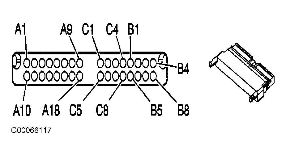 Courtesy of GENERAL MOTORS CORP.