Low Coolant Indicator
- If LOW COOLANT indicator comes on, but coolant level is okay, go to step 6). If LOW COOLANT indicator comes on intermittently while driving, go to step 11). If LOW COOLANT indicator does not come on and coolant level is low, disconnect coolant level sensor connector. Turn ignition switch to RUN position. Jumper terminal "B" (Light Green wire) of sensor connector to ground.
- If indicator does not come on, go to next step. If indicator comes on, check for open in Black wire from sensor to ground. If wire and connection are okay, replace coolant level sensor.
- Turn ignition off. Disconnect connector C200A (17-cavity female) from C200D (48-cavity male). See Fig 1
-4. Connectors C200A and C200D are located in forward light harness, between left kick panel and steering column. Connect a fused jumper wire between connector C200D terminal A17 (Yellow/Black wire) and ground. Turn ignition on.
- If indicator does not come on, go to next step. If indicator comes on, check terminal contact at connection C200A/C200D or for open in Yellow/Black wire or Light Green wire. If wires are okay, replace isolation diode.
- Check for open in Yellow/Black wire. If wire is okay, replace indicator bulb. If indicator still does not come on, check instrument cluster printed circuit. If no problems are found and indicator still does not come on, replace instrument cluster. See INSTRUMENT CLUSTER
under REMOVAL & INSTALLATION.
- Disconnect engine coolant level sensor connector. Turn ignition on. If indicator does not come on, replace coolant level sensor. If indicator comes on, go to next step.
- Remove low coolant relay from underhood relay center. If indicator remains on, go to next step. If indicator goes out, replace low coolant relay.
- Disconnect ignition switch connector C1 (4-cavity). If indicator remains on, go to next step. If indicator goes out, replace ignition switch.
- Disconnect connector C200A (17-cavity female) from C200D (48-cavity male). See Fig 1
-4. Connectors C200A and C200D are located in forward light harness, between left kick panel and steering column. If indicator goes out, repair short to ground in Light Green wire or Yellow/Black wire between connector C200A and engine coolant level sensor.
- If indicator remains on, repair short to ground in Yellow/Black wire between instrument cluster, ignition switch and connector C200D. If wire is okay, replace instrument cluster. See INSTRUMENT CLUSTER
under REMOVAL & INSTALLATION.
- Remove low coolant relay from underhood electrical center. Turn ignition on. Connect a test light between electrical center terminals G1 (Black wire) and G5 (Pink wire). If test light does not come on, go to next step. If test light comes on, go to step 13).
- Connect test light between electrical center terminal G5 (Pink wire) and ground. If test light comes on, repair open or poor connection in Black wire. If test light does not come on, check for blown fuse No. 12, or check for open or short to ground in Pink wire.
- Turn ignition off. Disconnect engine coolant level sensor. Connect fused jumper wire between ground and sensor connector terminal "B" (Light Green wire). With a test light connected to battery voltage, probe underhood electrical center terminals G2 and G4 (Light Green wires).
- If test light comes on at both connections, go to next step. If test light does not come on at both terminals, repair open in appropriate Light Green wire between underhood electrical center terminal and low coolant sensor.
- Check for open or poor connection in Yellow/Black wire between instrument cluster and splice to Light Green wire near secondary air pump breakout. If wire is okay, replace low coolant relay.
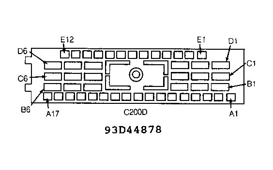 Courtesy of GENERAL MOTORS CORP.
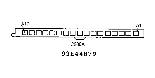 Courtesy of GENERAL MOTORS CORP.
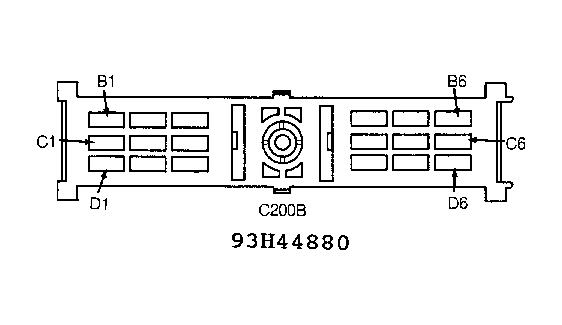 Courtesy of GENERAL MOTORS CORP.
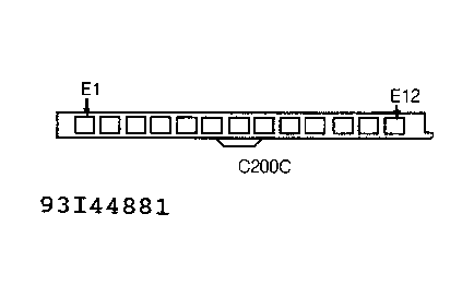 Courtesy of GENERAL MOTORS CORP.