Preliminary Information
- Except while taking resistance readings, ignition switch should be in RUN position. Ensure negative battery cable is disconnected.
- Perform all resistance measurements to ground unless a specific terminal number is given. If voltage or resistance is correct, check circuit for malfunction using appropriate test.
- If voltage or resistance is correct but function using those terminals is incorrect, check instrument cluster bulbs. If bulbs are okay, replace instrument cluster. See INSTRUMENT CLUSTER
under REMOVAL & INSTALLATION.
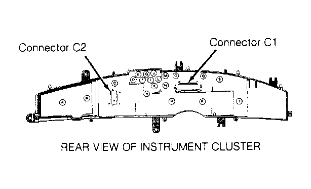 Courtesy of GENERAL MOTORS CORP.
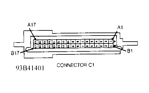 Courtesy of GENERAL MOTORS CORP.
 INSTRUMENT CLUSTER CONNECTOR C1 PINOUT TEST
| Cavity |
Wire Color |
Description |
| A1 |
BLK/PNK |
Coolant Temp. Indicator |
| A1 |
BLK/PNK |
Hot Coolant Input |
| A2 |
TAN |
Oil Pressure Indicator |
| A2 |
TAN/BLK |
Oil Pressure Gauge |
| A3 |
BLK |
Ground |
| A4 |
GRY |
Illumination Input |
| A5 |
TAN/WHT |
Brake Indicator |
| A6 |
PNK/BLK |
Ignition Power |
| A7 |
YEL |
Chime Control Output |
| A8 |
BLK/WHT |
Ground |
| A9 |
WHT/BLK |
Coolant Temp. Gauge |
| A11 |
BLK/WHT |
Washer Fluid Level Input |
| A12 |
BRN/WHT |
Check Oil Indicator |
| A13 |
BRN |
Volts Indicator Input |
| A13 |
BRN |
Volts Gauge Input |
| A14 |
PPL |
Fuel Gauge Sender Input |
| A15 |
PNK/BLK |
Ignition Power |
| A16 |
DK BLU |
Right Turn Indicator |
| A17 |
BLK/WHT |
Ground |
| B1 |
DK GRN |
Vehicle Speed Input |
| B2 |
PNK/BLK |
Ignition Power |
| B3 |
BLK |
Ground |
| B4 |
PNK/BLK |
Ignition Power |
| B5 |
BLK |
Ground |
| B6 |
GRY |
Illumination Input |
| B7 |
WHT |
ABS Indicator |
| B8 |
YEL |
Fasten Belts Indicator |
| B9 |
ORN |
Battery Voltage |
| B10 |
DK GRN |
Security Indicator |
| B11 |
BRN/WHT |
Service Engine Soon Indicator |
| B12 |
BRN |
SIR Indicator |
| B13 |
PPL/WHT |
Traction Control Indicator |
| B15 |
WHT |
Tachometer Input |
| B16 |
LT GRN |
High Beam Indicator |
| B17 |
LT BLU |
Left Turn Indicator |