Control Arm Bushing: Installation
- Install bushing as follows:
- Invert J 28685-2 and install into J 9519-23.
- Use J 9519-23 in place with J 9519-16, and install new bushing.
- Install bushing bolt to align tool and bushing into place. Cut-outs on rubber portion of bushing must face front and rear.
- Press bushing into control arm by turning bolt. When bushing is in proper position, the end of it will line up with scribe line on J 28685-2 (sight through gage hole). See Fig 1
.
- Install bracket to control arm. Tighten nut to specification. See TORQUE SPECIFICATIONS
.
- Thoroughly clean control arm bracket-to-underbody bolts. Apply Loctite(R) sealer (part number 1052624 or equivalent) to threads.
- Raise control arm into position. Install control arm bracket-to-underbody attaching bolts, and tighten to specification. See TORQUE SPECIFICATIONS
.
- Replace spring and insulator. Install shock lower attaching nut and bolt, and tighten to specification. See TORQUE SPECIFICATIONS
.
- Install brakeline bracket to frame. Tighten screws to specification. See TORQUE SPECIFICATIONS
.
- On right side only, reconnect brake cables to bracket, and reinstall brake cable to hook. Adjust cable as necessary. See appropriate article in BRAKES.
- Remove rear axle support and lower vehicle.
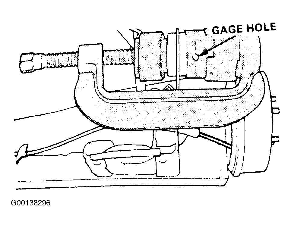 Courtesy of GENERAL MOTORS CORP.