Radiator Cooling Fan Motor: Testing and Inspection
Chart C-12 - Coolant Fan Control Circuit:
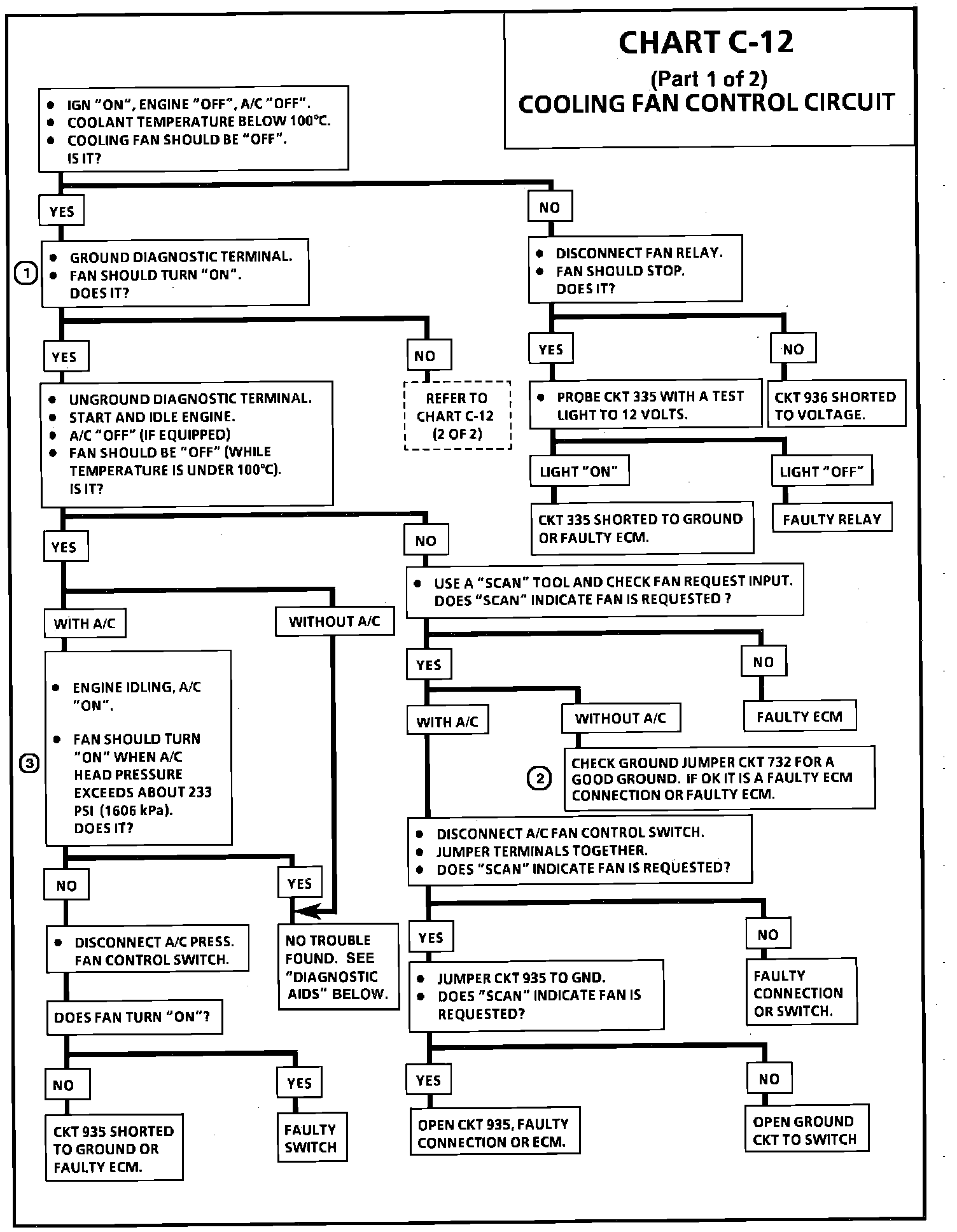
Wiring Diagram for Coolant Fan Control Circuit:
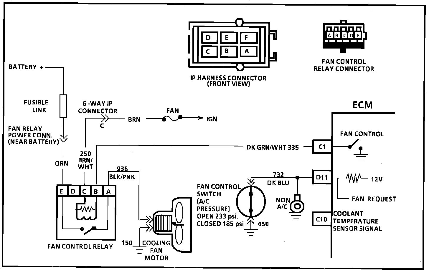
CHART C-12 COOLING FAN CONTROL CIRCUIT
Circuit Description:
The cooling fan is totally controlled by the ECM based on inputs from the coolant sensor and fan control switch. The fan should run if coolant temperature is greater than about 105 degrees C (221 degrees F). Battery voltage is supplied to the fan relay on terminal "E" and ignition voltage to terminal "C". Grounding CKT 335 (relay terminal "B") will energize the relay and supply battery voltage to the fan motor. Once the fan relay is energized, by the ECM, it will remain "ON" for a minimum of 5 seconds. The ECM will remove the ground to CKT 335 if vehicle speed is over 40 mph unless the engine is overheating. The fan control switch, mounted in the A/C high pressure line, will open when head pressure exceeds 233 psi (1600 kPa) and this input causes the ECM to ground CKT 335. On a non A/C vehicle, CKT 732 is connected to ground to prevent fan from operating at all times. If a Code 14 or 15 sets or the ECM is operating in the fuel back-up mode the ECM will turn "ON" the cooling fan.
Test Description: Step numbers refer to step numbers on diagnostic chart.
1. With the diagnostic terminal grounded, the cooling fan control driver will close, which should energize the fan control relay.
2. If the A/C fan control switch or circuit is open, the fan would run whenever the engine is running.
3. With A/C clutch engaged, the A/C fan control switch should open, when A/C high pressure exceeds about 200 psi (1380 kPa). This signal should cause the ECM to energize the fan control relay.
Diagnostic Aids:
If the owner complained of an overheating problem, it must be determined if the complaint was due to an actual boil over or the hot light or temperature gauge indicated overheating.
If the gauge or light indicates overheating, but no boilover is detected, the gauge circuit should be checked. The gauge accuracy can also be checked by comparing the coolant sensor reading us "Scan" tool and comparing its reading with the gauge reading.
If the engine is actually overheating and the gauge indicates overheating, but the cooling fan is not coming "ON", the coolant sensor has probably shifted out of calibration and should be replaced.
If the engine is overheating, and the cooling fan is "ON", the cooling system should be checked.
Chart C-12 - Coolant Fan Control Circuit:
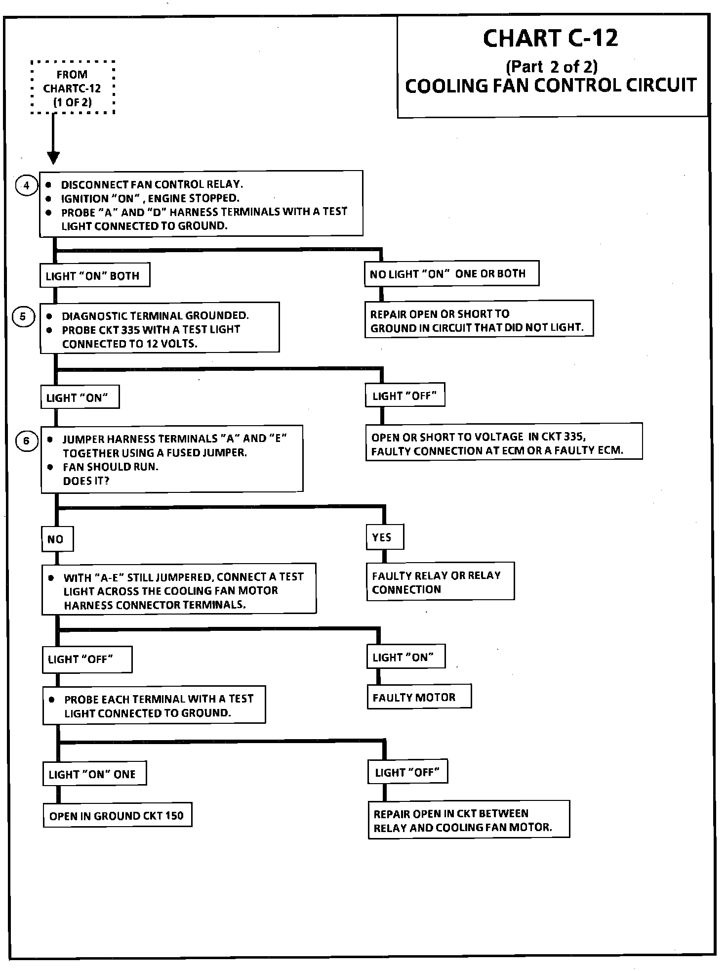
CHART C-12 COOLING FAN CONTROL CIRCUIT
Test Description: Step numbers refer to step numbers on diagnostic chart.
4. 12 volts should be available to both terminal E & C, when the ignition is "ON".
5. This test checks the ability of the ECM to ground CKT 335. The SES light should also be flashing, at this point. If it isn't flashing, see CHART A-2.
6. If the fan does not turn "ON", at this point, CKT 936 or CKT 150 is open, or the cooling fan motor is faulty.