On-Car Service
FIGURE 1 - CALIPER ASSEMBLY DISASSEMBLED VIEW:
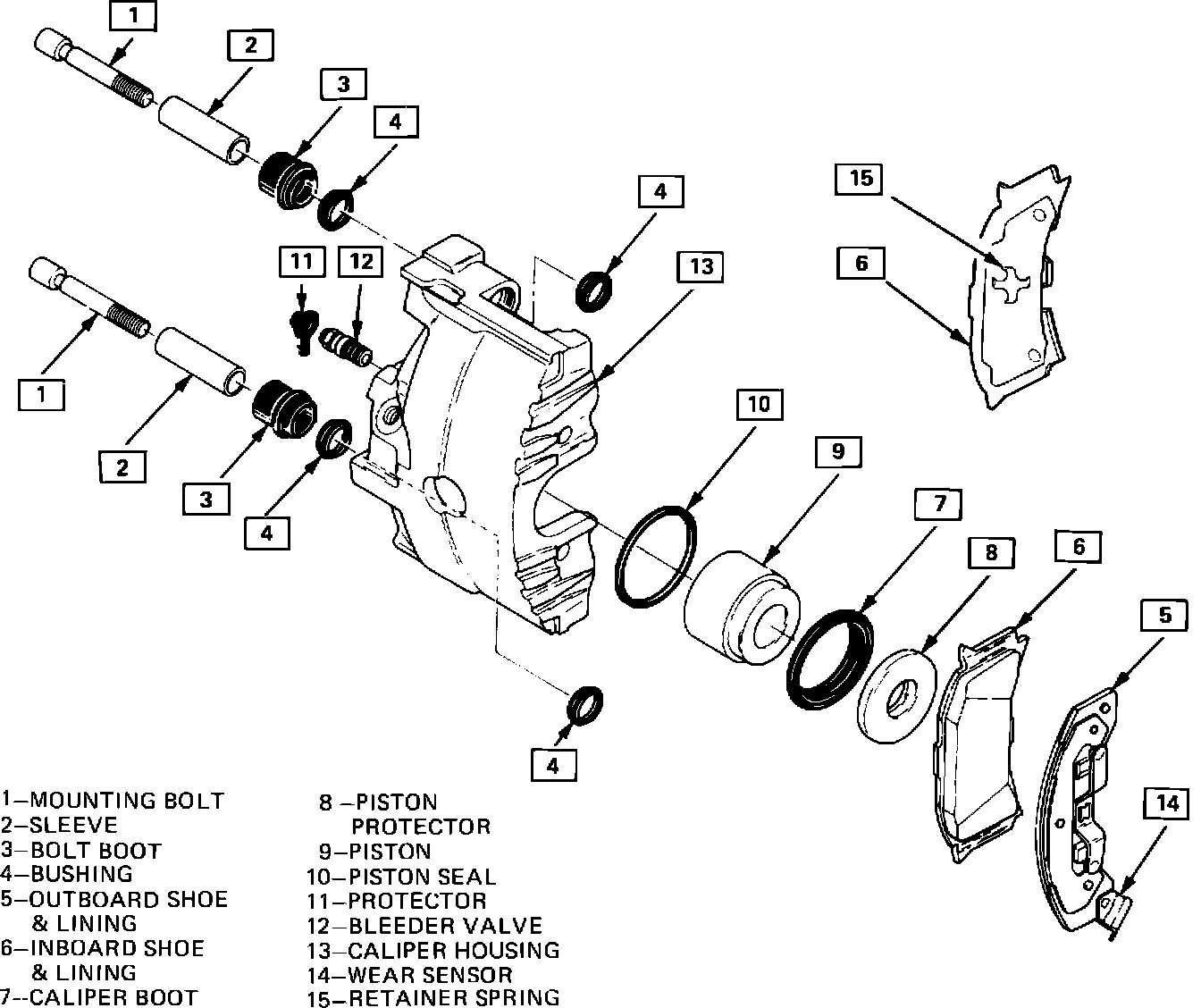
CALIPER ASSEMBLY
Figures 2 through 6
v Remove or Disconnect
1. 2/3 of brake fluid from master cylinder assembly.
2. Raise car and suitable support.
^ Mark relationship of wheel to axle flange.
3. Wheel and tire.
^ Reinstall two inverted lug nuts to retain rotor.
FIGURE 2 - COMPRESSING PISTON:
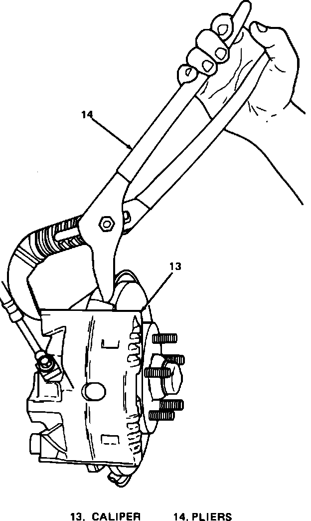
4. Bottom piston into caliper bore to provide clearance between linings and rotor (Figure 2).
^ Position 12-inch adjustable pliers (14) over caliper support bracket and the inboard caliper housing (Figure 2).
FIGURE 3 - CALIPER ATTACHMENT:
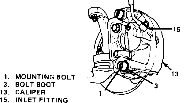
5. Bolt attaching inlet fitting (15), only if caliper is to be removed from vehicle for unit repair (overhaul). If only shoe and linings are being replaced, there is no need to disconnect inlet fitting (Figure 3).
FIGURE 4 - SUSPENDING CALIPER:
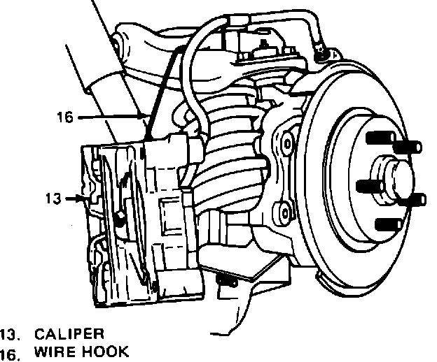
FIGURE 5 - LUBRICATING CALIPER CAVITY:
^ Plug openings in caliper and pipe to prevent fluid loss and contamination.
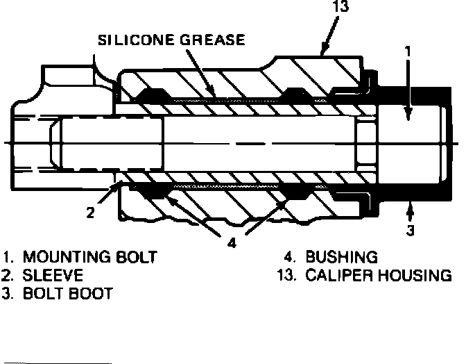
6. Boots (3), mounting bolts (1), and sleeves (2) using No. 50 Torx wrench.
7. Caliper (13) from rotor and mounting bracket (17). If only shoe and linings are being replaced, suspend with a wire hook (16) from strut.
Inspect
^ Mounting bolts and sleeves for corrosion.
^ If corrosion is found, use new parts, including bushings, when installing caliper.
^ Do not attempt to polish away corrosion.
Important
^ See NOTICE on page 5-1.
Install or Connect
1. Liberally fill both cavities in housing (13) between bushings (4) with silicone grease.
2. Sleeves (2) in caliper (13).
3. Caliper (13) over rotor in mounting bracket (17).
4. Mounting bolts (1) to 28-47 N-m (21-35 ft.lbs.).
5. Boots (3).
^ Make sure boots are mounted securely.
v Measure
FIGURE 6 - CALIPER TO BRACKET CLEARANCE:
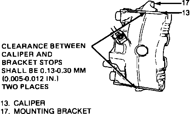
Figure 6
^ Clearance between caliper (13) and bracket (17) stops.
^ If necessary, remove caliper and file ends of bracket (17) stops to provide proper clearance (Figure 6).
6. Inlet fitting (15) with new washers, if removed, to 24-40 N-m (18-30 ft.lbs.).
7. Wheels and tires, aligning previous marks.
^ Remove lug nuts securing rotor to hub.
^ Lower car.
^ Torque lug nuts. See WHEELS and TIRES.
8. Fill master cylinder to proper lever with clean brake fluid.
FIGURE 7 - SHOE AND LINING ASSEMBLY:
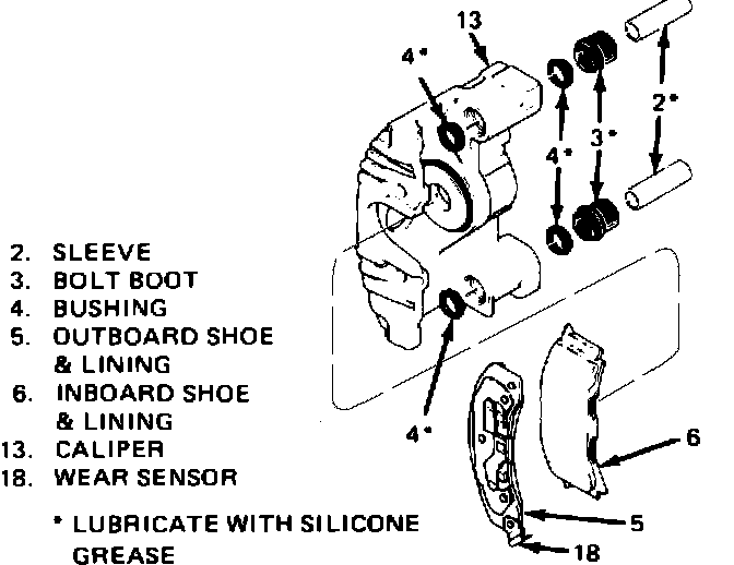
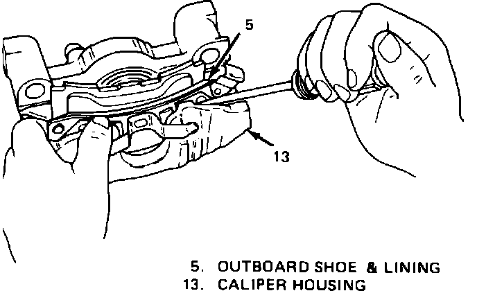
FIGURE 8 - REMOVING OUTBOARD SHOE:
^ Bleed caliper if inlet fitting was removed.
^ Recheck fluid level.
SHOE AND LINING ASSEMBLIES
Figures 7 through 10
Remove or Disconnect
1. Caliper as previously described.
2. Outboard shoe and lining (5) (Figures 7 & 8).
^ Use screwdriver to disengage buttons on shoe from holes in caliper housing (13).
3. Inboard shoe and lining (6).
4. Bushings (4) from grooves in mounting bolt holes.
Install or Connect
1. Lubricated new bushings (4) in grooves in mounting bolt holes.
FIGURE 9 - INSTALLING INBOARD SHOE AND LINING:
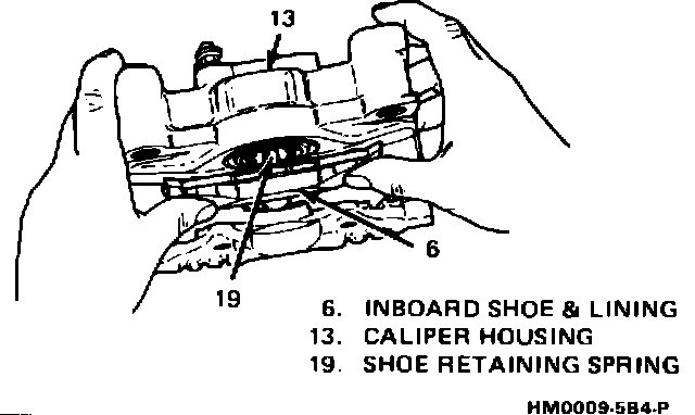
2. Inboard shoe and lining (6) by snapping retainer spring (19) into center hole of piston (9). Shoe retainer spring is already staked to the inboard
shoe. Shoe must lay flat against piston with piston retracted in caliper housing (13) (Figure 9).
FIGURE 10 - INSTALLING OUTBOARD SHOE & LINING:
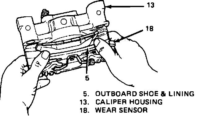
3. Outboard shoe and lining (5) with wear sensor (18) at leading edge of caliper during forward wheel rotation. Back of shoe must lay flat against caliper (Figure 10).
4. Caliper as previously described.
5. Apply approximately 778 N (175 lbs.) force three times to brake pedal to seat linings.