Removal & Installation
- Disconnect and isolate negative battery cable. Remove cluster. Remove four cluster back cover retaining screws and remove cover. Disconnect wire connectors and two wire strips from speedometer printed circuit board. See Fig 1.
- Remove three printed circuit board retaining screws and remove two screws located at base of connector. See Fig 2. Loosen screws on fuel and temp printed circuit board to allow speedometer printer circuit board to be removed. Release locking tabs and remove speedometer PC board. See Figure. To install, reverse removal procedures.
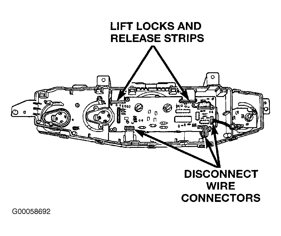 Courtesy of CHRYSLER CORP.
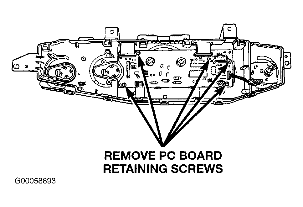 Courtesy of CHRYSLER CORP.