Horn Inoperative
- Check fuse No. 14 (40-amp) in Power Distribution Center (PDC) and fuse No. 8 (20-amp) in junction block. Junction block is located under left front of instrument panel. If fuses are okay, go to next step. If either fuse is blown, go to step 7)
.
- Remove horn relay from junction block. Using ohmmeter, check for continuity to ground at horn relay terminal No. 7 in junction block while pressing horn switch. See Fig 1
. If continuity exists, go to next step. If continuity does not exist, go to step 4)
.
- Connect jumper wire between horn relay terminal No. 8 and horn relay terminal No. 10 in junction block. If horns do not sound, go to step 5)
. If horns sound, replace horn relay.
- Remove air bag/horn pad from steering wheel. See HORN SWITCH
under REMOVAL & INSTALLATION. Using ohmmeter, check for continuity between horn switch connector terminals while pressing horn switch. If continuity does not exist, replace air bag/horn pad. If continuity exists, repair open in wiring between horn switch and horn relay. See WIRING DIAGRAMS
.
- Install horn relay. Disconnect horn electrical connectors. Using voltmeter, check for voltage between horn harness terminals while pressing horn switch. If no voltage exists, go to next step. If voltage exists, replace horn(s).
- Check for voltage between Dark Green/Pink wire terminal at horn and ground while pressing horn switch. If voltage exists, repair horn ground circuit. If voltage does not exist, repair open in Dark Green/Pink wire(s) between horn and horn relay.
- Ensure battery is fully charged and terminal connections are okay. Go to next step. Check voltage at both sides of fuse No. 8. If voltage exists at both sides, go to step 2)
. If voltage does not exist on one side of fuse, fuse is blown. Go to next step.
- Remove fuse. Connect ammeter across fuse terminals. Check amperage draw of horn circuit. If amperage draw is greater than 20 amps without horn switch depressed, circuit is grounded between fuse and horn relay. Go to next step. If amperage draw is greater than 20 amps with horn switch depressed, circuit is grounded between horn relay and horn. Go to step 11
.
- Remove horn relay from junction block. If amperage draw drops to zero amps, horn switch or circuit is shorted. See WIRING DIAGRAMS
. If amperage draw does not drop, go to next step.
- Disconnect both horns. If amperage draw does not drop with both horns disconnected and horn switch depressed, go to step 12
. If amperage draw drops, go to next step.
- Ensure one horn connector is disconnected and other horn connector is connected. If amperage draw drops with one horn disconnected and other horn sounds, reverse procedure, and replace faulty horn.
- Ensure both horn connectors are disconnected. Check continuity between horn relay terminal No. 10 and ground. If continuity does not exist, no problem is indicated at this time. Test is complete. If continuity exists, repair shorted circuit. If amperage draw does not drop to zero amps, repair short in junction block.
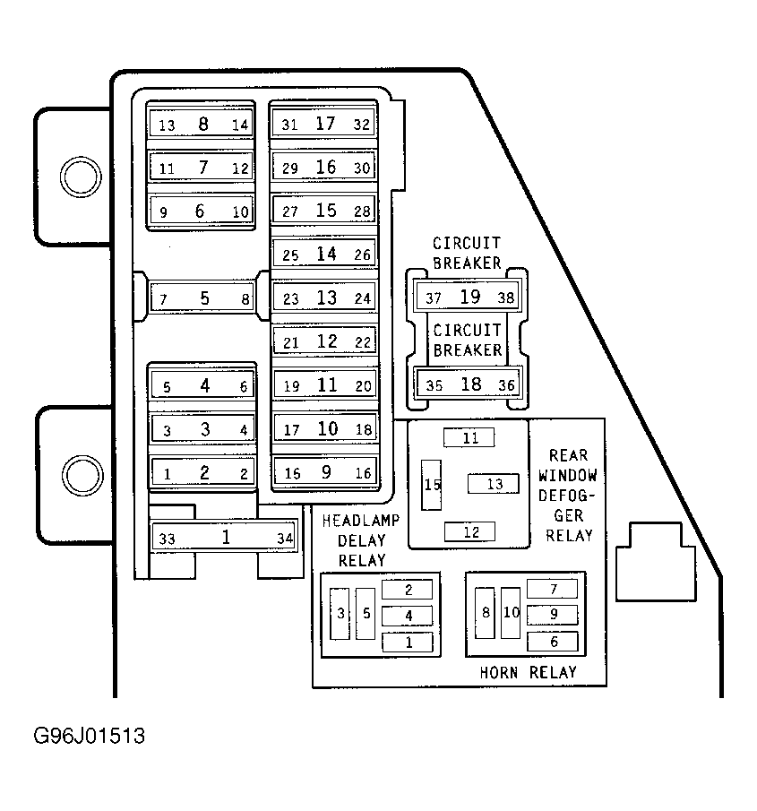 Courtesy of CHRYSLER CORP.