Instrument Cluster Inoperative
- Disconnect instrument cluster Gray, 24-pin connector. Turn ignition switch to RUN position. Using DVOM, check voltage between instrument cluster harness connector terminal B9 (Purple wire) and ground. See Figure
. If battery voltage exists, go to next step. If battery voltage does not exist, go to step 5
.
- Check voltage between instrument cluster harness connector terminal A1 (Orange wire) and ground. If battery voltage exists, go to next step. If battery voltage does not exist, go to step 7
.
- Check voltage between instrument cluster harness connector terminals B9 (Purple wire) and B10 (Black/White wire). If battery voltage is present, go to next step. If battery voltage is not present, go to step 8
.
- Check voltage between instrument cluster harness connector terminals A1 (Orange wire) and A4 (Black/White wire). If battery voltage exists, go to step 6
. If battery voltage does not exist, go to step 8
.
- Repair open in circuit No. 1600 (Purple wire) between left instrument panel wiring harness junction block connector C1 and instrument cluster. See Fig 1
. Recheck system operation.
- Replace instrument cluster. See INSTRUMENT CLUSTER
under REMOVAL & INSTALLATION. Recheck system operation.
- Repair open in circuit No. 1440 (Orange wire) between left instrument panel wiring harness junction block connector C1 and instrument cluster. Recheck system operation.
- Repair open in circuit No. 151 (Black/White wire) between instrument cluster and ground. Recheck system operation.
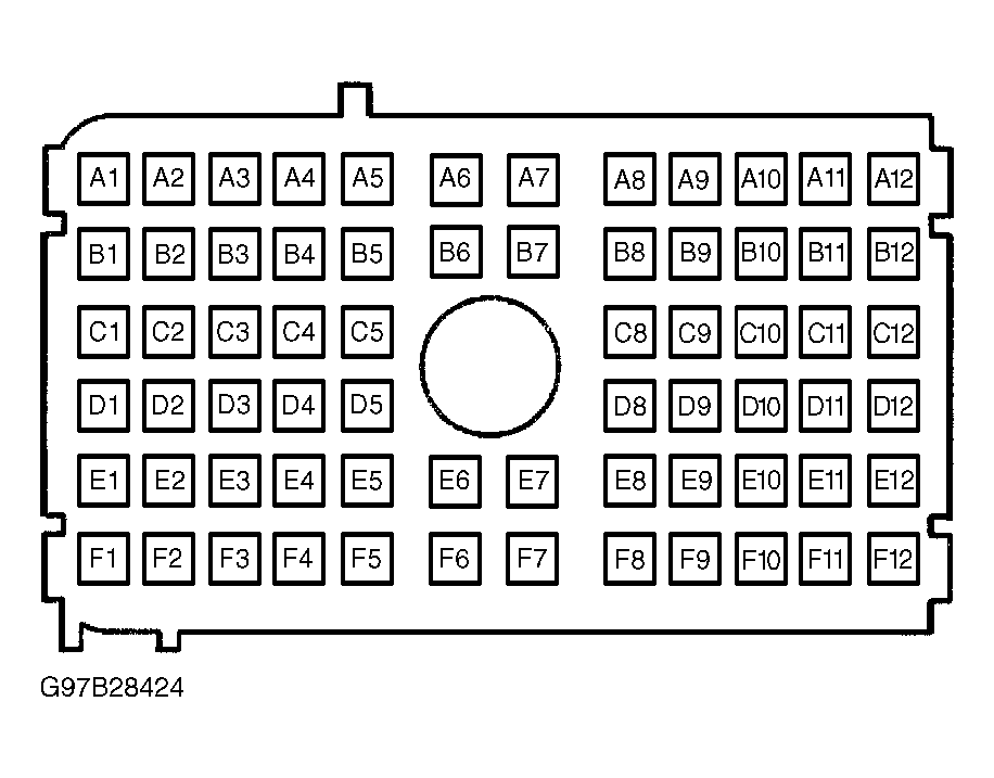 Courtesy of GENERAL MOTORS CORP.