Instrument Cluster Tachometer Malfunctioning
- If BFC diagnostic system check was performed, go to next step. If BFC diagnostic system check was not performed, see appropriate
BODY CONTROL MODULES article.
- Connect scan tool. Start engine. Using scan tool, read BFC-to-instrument cluster data. If tach signal display is ACTIVE, go to step 5
. If tach signal display is not ACTIVE, go to next step.
- Using DVOM set on AC voltage, check voltage at tach test point located in underhood wiring harness junction block. See Fig 1
. If AC voltage exists, go to next step. If AC voltage does not exist, go to step 5
.
- Replace instrument cluster. See INSTRUMENT CLUSTER
under REMOVAL & INSTALLATION. Recheck system operation.
- Check for short to ground on White wire (circuit No. 121). See WIRING DIAGRAMS. If short to ground exists, go to next step. If no short to ground exists, go to step 7
.
- Repair short to ground in circuit No. 121 (White wire). Recheck system operation.
- Check resistance of White wire (circuit No. 121). See WIRING DIAGRAMS
. If resistance is more than 2 ohms, go to next step. If resistance is 2 ohms or more, go to step 9
.
- Repair open circuit No. 121 (White wire). Recheck system operation.
- Replace PCM. Recheck system operation.
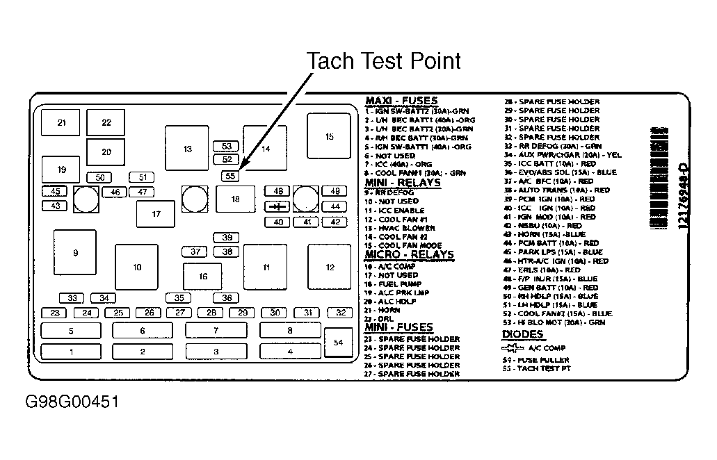 Courtesy of GENERAL MOTORS CORP.
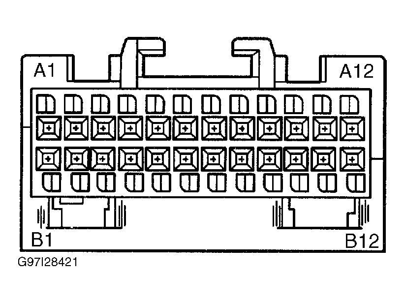 Courtesy of GENERAL MOTORS CORP.