TPMS Control Unit Inputs and Outputs 20P Connector
WARNING: This page is about a different car, the 2013 Acura MDX, 2012 Acura MDX, 2011 Acura MDX, and 2010 Acura MDX. However, it is still accessible from the selected car via links, so may be relevant.
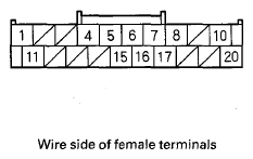 Courtesy of AMERICAN HONDA MOTOR CO., INC.
| Terminal number |
Wire color |
Terminal sign (Terminal name) |
Description |
Signal |
| Terminal |
Conditions |
Voltage |
| 1 |
WHT |
F-CAN A H (CAN communication signal high) |
Sends the communication signal |
--- |
Ignition switch ON (II) |
Pulses |
| 4 |
BLK |
GND (Ground) |
Ground for the TPMS control unit |
4-GND |
At all times |
Less than 0.1 V |
| 5 |
GRY |
LF LF SIG. (LF low frequency signal) |
Sends the signal to the left-front initiator |
5-GND |
For the first 5-16 seconds after turning the ignition switch to ON (II) |
Pulses 0-2 V |
| With ignition switch ON (II) for more than 5-16 seconds |
Less than 0.1 V |
| 6 |
LT GRN |
RF LF SIG. (RF low frequency signal) |
Sends the signal to the right-front initiator |
6-GND |
For the first 5-16 seconds after turning the ignition switch to ON (II) |
Pulses 0-2 V |
| With ignition switch ON (II) for more than 5-16 seconds |
Less than 0.1 V |
| 7 |
ORN |
K-LINE (Data link connector) |
Communications with the HDS |
--- |
--- |
--- |
| 8 |
YEL |
IG1 (Ignition switch 1) |
Power source for activating the system |
8-GND |
Ignition switch ON (II) |
Battery voltage (about 12V) |
| Ignition switch OFF |
Less than 0.1 V |
| 10 |
WHT |
+ B (Battery positive) |
Power source for the TPMS control unit |
10-GND |
At all times |
Battery voltage (about 12V) |
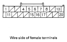 Courtesy of AMERICAN HONDA MOTOR CO., INC.
| Terminal number |
Wire color |
Terminal sign (Terminal name) |
Description |
Signal |
| Terminal |
Conditions |
Voltage |
| 11 |
RED |
F-CAN A L (CAN communication signal low) |
Sends the communication signal |
--- |
Ignition switch ON (II) |
Pulses |
| 15 |
LT BLU |
LF GND (LF low frequency ground) |
Ground for the initiators |
15-GND |
Ignition switch ON (II) |
Less than 0.1 V |
| 16 |
PNK |
LR LF SIG. (LR low frequency signal) |
Sends the signal to the left-rear initiator |
16-GND |
For the first 5-16 seconds after turning the ignition switch to ON (II) |
Pulses 0-2 V |
| With ignition switch ON (II) for more than 5-16 seconds |
Less than 0.1 V |
| 17 |
GRY |
RR LF SIG. (RR low frequency signal) |
Sends the signal to the right-rear initiator |
17-GND |
For the first 5-16 seconds after turning the ignition switch to ON (II) |
Pulses 0-2 V |
| With ignition switch ON (II) for more than 5-16 seconds |
Less than 0.1 V |
| 20 |
BRN |
LF PWR. (LF low frequency power) |
Power source for the initiators |
20-GND |
For 5 seconds with ignition switch ON (II) |
About 7 V |
| After 5 seconds with ignition switch ON (II) |
--- |