DTC 41, 42, 45, 46, 51, 52, 55, 56, 63: (ABS Actuator Solenoid Valve Or Solenoid Valve Relay)
- Check ABS solenoid relay fusible link "f" (40-amp). Fusible link "f" is located in the fusible link and fuse box in the engine compartment. See Fig 1
and Fig 2
. If fusible link is okay, go to next step. If fusible link is blown, go to step 6
.
- Check fuse No. 31 (10-amp), located in passenger compartment fuse block. See Figure
. If fuse is okay, go to next step. If fuse is blown, go to step 8
.
- Disconnect ABS actuator/control unit 31 pin harness connector. See Figure
. Check terminals for damage or loose connection. If a problem is found, repair as necessary. Reconnect connector. Perform self-diagnostics again. See SELF-DIAGNOSTICS
. Check ABS warning light. If ABS warning lamp stays on, go to next step. If ABS warning lamp does not stay on, system is okay.
- Check ABS ground circuit. See ABS ACTUATOR/CONTROL UNIT GROUND
under PRELIMINARY CHECKS. If a problem is found, repair as necessary. If ground circuit is okay, go to next step.
- Disconnect ABS actuator/control unit 31 pin harness connector. Measure voltage between chassis ground and ABS actuator/control unit 31 pin harness connector terminal No. 18. See Figure
. If battery voltage is present, replace ABS actuator/control unit. See ABS ACTUATOR/CONTROL UNIT
under REMOVAL & INSTALLATION. If battery voltage is not present, check for faulty circuit between ABS actuator/control unit and fusible link. Repair as necessary.
- Replace fusible link. Turn ignition on and observe fusible link. If fusible link blows, go to next step. If fusible link does not blow, system is okay.
- Turn ignition Off. Disconnect ABS actuator/control unit 31 pin harness connector. Check continuity between chassis ground and ABS actuator/control unit 31 pin harness connector terminal 18. If continuity exists, replace ABS actuator/control unit. If continuity does not exist, check harness connector for open or short between ABS actuator/control unit and fusible link. Repair as necessary.
- Replace fuse. Turn ignition on and observe fuse. If fuse does not blow, system is okay. If fuse blows, check for short in circuit between ABS actuator/control unit and fuse. If a problem exist, repair as necessary. Perform self-diagnostics again. See SELF-DIAGNOSTICS
.
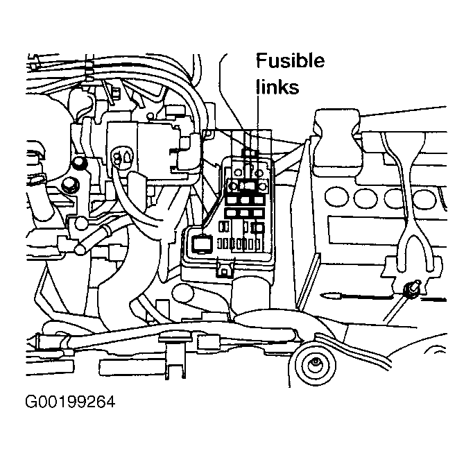 Courtesy of NISSAN MOTOR CO., U.S.A.
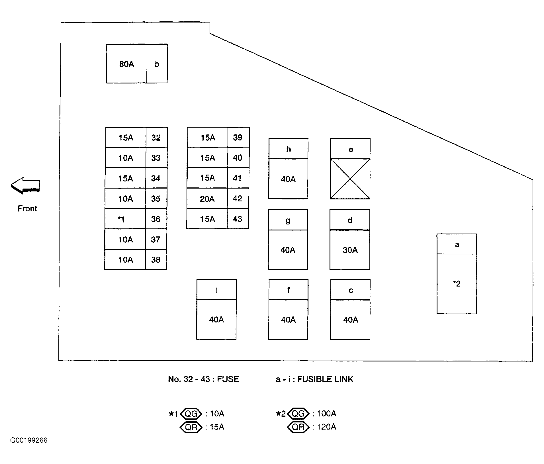 Courtesy of NISSAN MOTOR CO., U.S.A.