Power Supply & Ground Circuit Check
- Check Power Supply
Disconnect instrument cluster harness connectors. On models with tachometer, measure voltage between ground and terminal No. 41 (Yellow wire) or No. 42 (Red/Black wire) at appropriate instrument cluster harness connector. On models without tachometer, measure voltage between ground and terminal No. 25 (Red/Black wire) or No. 26 (Yellow wire) at appropriate instrument cluster harness connector. See Fig 1
and Fig 2
. Ensure battery voltage is present on terminals No. 25 (Red/Black wire) and No. 42 (Red/Black wire) with ignition switch in OFF, ACC and ON positions. If voltage is as specified, go to next step. If voltage is not as specified, go to step 3
.
- Using DVOM, measure voltage between ground and terminals No. 26 (Yellow wire) or No. 41 (Yellow wire) at appropriate instrument cluster harness connector. Ensure battery voltage is present only with ignition switch in ON position. If voltage is as specified, go to step 4
. If voltage is not specified, go to next step.
- Check condition of fuses No. 30 (10-amp) and No. 12 (10-amp), located in fuse block. See WIRING DIAGRAMS
. Check for open or short in wiring harness between fuse and instrument cluster. Repair as necessary.
- Check Ground Circuit
Disconnect instrument cluster harness connectors. On models with tachometer, check for continuity between ground and terminal No. 48 (Black wire) at appropriate instrument cluster harness connector. On models without tachometer, check for continuity between ground and terminal No. 27 (Black wire) at appropriate instrument cluster harness connector. See Fig 1
or Fig 2
. If continuity is present, power supply and ground circuits are okay. If continuity is not as specified, repair open or poor connection in ground circuit (Black wire).
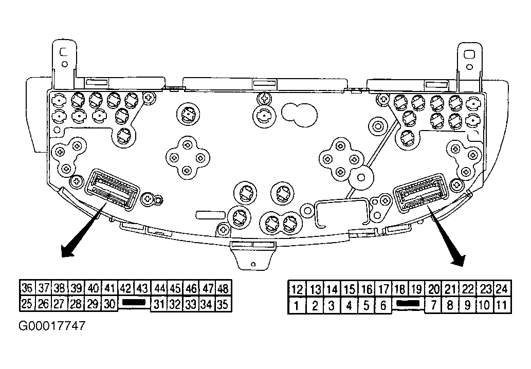 Courtesy of NISSAN MOTOR CO., U.S.A.
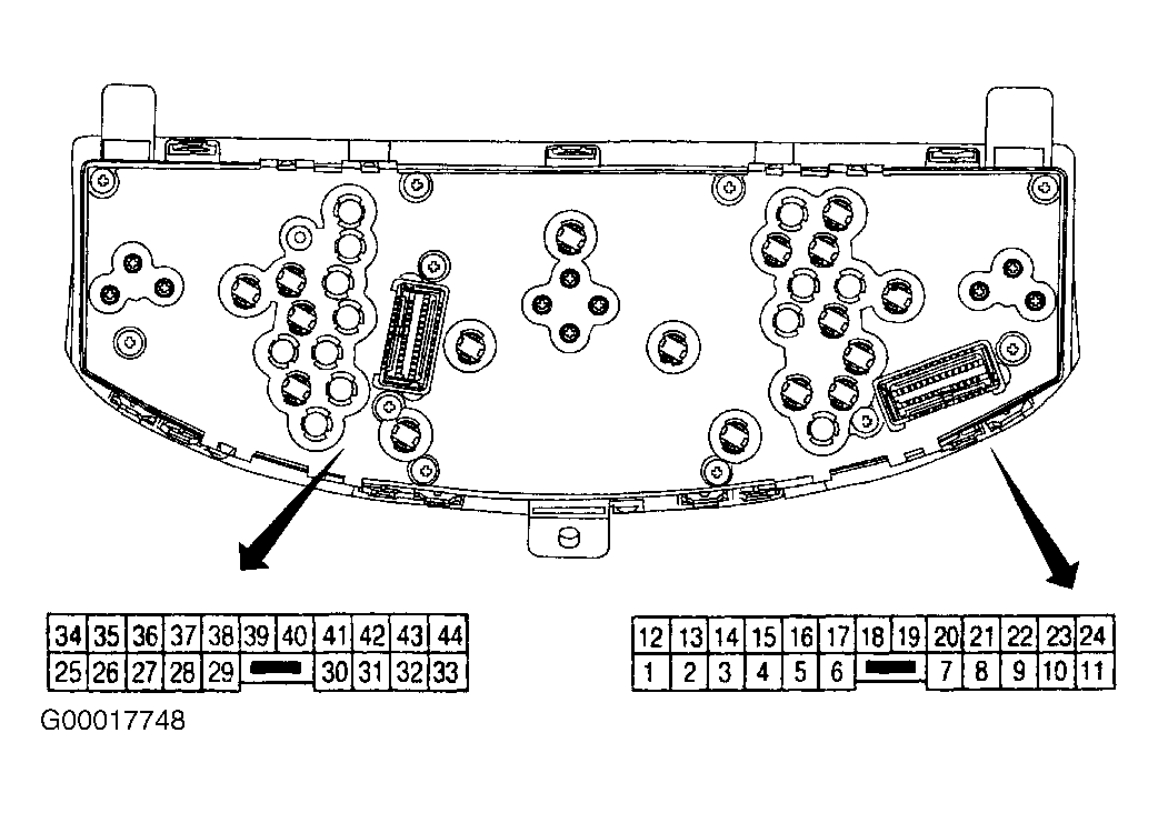 Courtesy of NISSAN MOTOR CO., U.S.A.