Inspection and Overhaul
CONTROL VALVE ASSEMBLY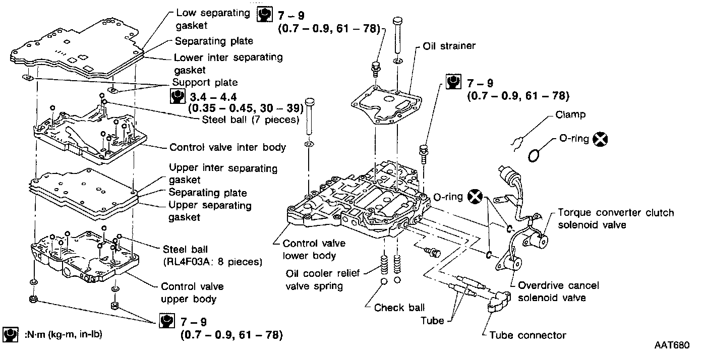
DISASSEMBLY
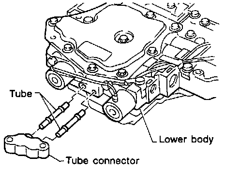
1. Remove tube connector and tube from control valve lower body.
2. Disassemble upper, inter and lower bodies.
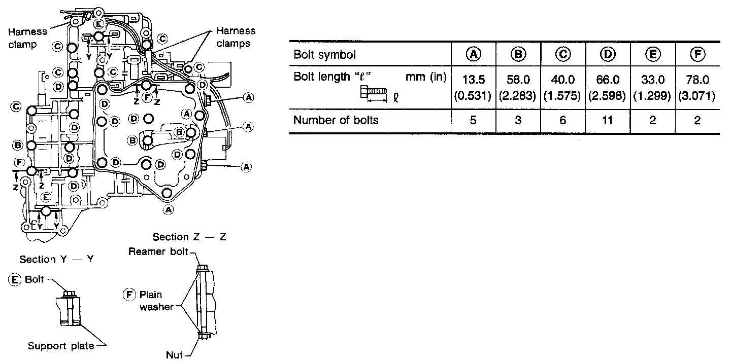
Bolt length, number and location:
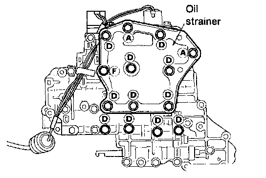
a. Remove bolts (A), (D) and (F) and remove oil strainer from control valve assembly.
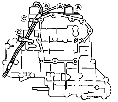
b. Remove overdrive cancel solenoid valve and torque converter clutch solenoid valve from control valve assembly.
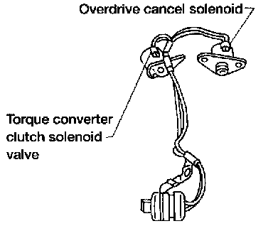
c. Remove O-rings from overdrive cancel solenoid valve, torque converter clutch solenoid valve and harness terminal body.
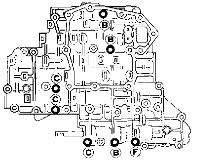
d. Place upper body facedown, and remove bolts (B), (C) and (F).
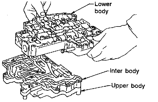
e. Remove lower body from inter and upper body.
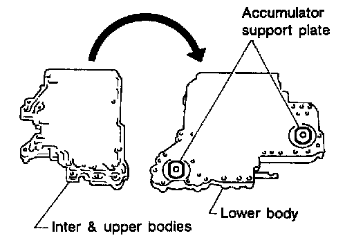
f. Turn over lower body, and remove accumulator support plate.
g. Remove separating plate and separating gasket from lower body.
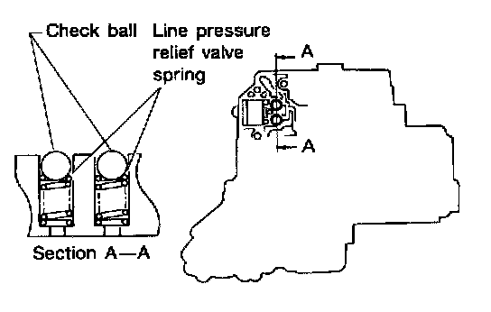
h. Remove check balls and relief valve springs from lower body.
- Be careful not to lose check balls and relief valve springs.
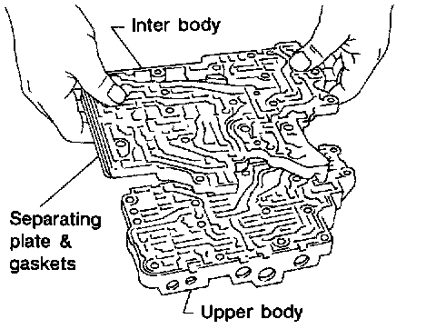
i. Remove inter body with separating plate and separating gasket from upper body.
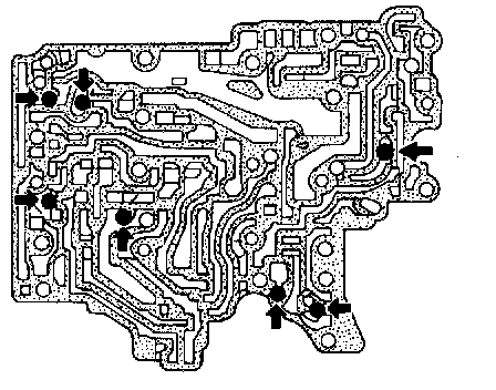
j. Check to see that check balls are properly positioned in inter body and then remove them.
- Be careful not to lose check balls.
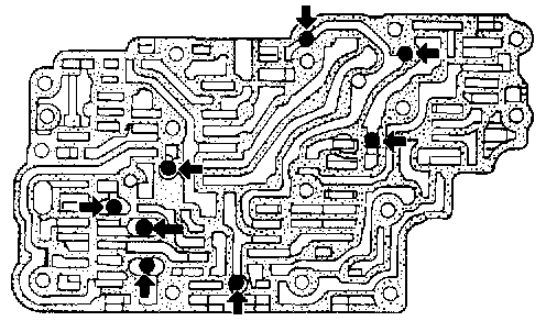
k. Check to see that check balls are properly positioned in upper body and then remove them.
- Be careful not to lose check balls.
INSPECTION
Lower and Upper Bodies
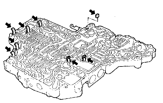
- Check to see that retainer plates are properly positioned in lower body.
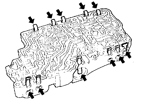
- Check to see that retainer plates are properly positioned in upper body.
- Be careful not to lose these parts.
Oil Strainer
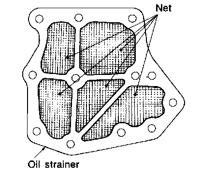
- Check wire netting of oil strainer for damage.
Overdrive Cancel Solenoid Valve
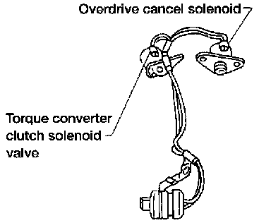
- Measure resistance.
Torque Converter Clutch Solenoid Valve
- Measure resistance.
Oil Cooler Relief Valve Spring
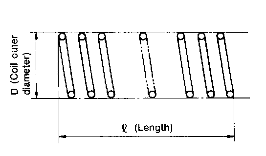
- Check springs for damage or deformation.
- Measure free length and outer diameter
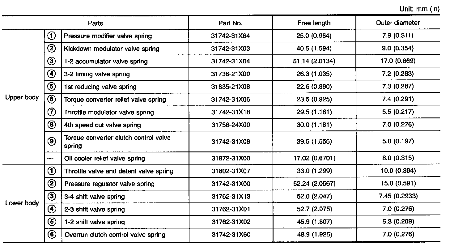
Inspection standard: Refer to image.
ASSEMBLY
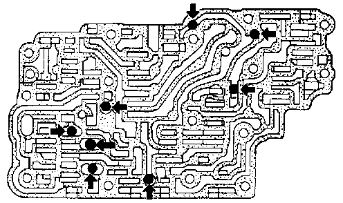
1. Install upper, inter and lower body.
a. Place oil circuit of upper body face up. Install steel balls in their proper positions.
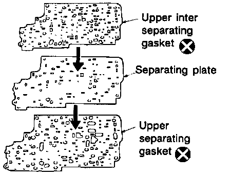
b. Install upper separating gasket, upper inter separating gasket and upper separating plate in order shown in illustration.
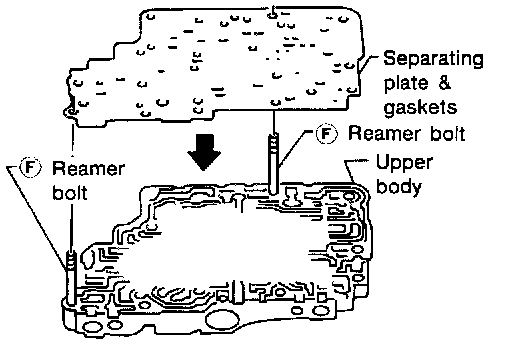
c. Install reamer bolts (F) from bottom of upper body. Using reamer bolts as guides, install separating plate and gaskets as a set.
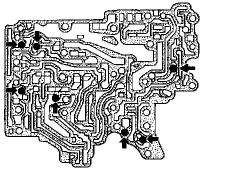
d. Place lower body side of inter body face up. Install steel balls in their proper positions.
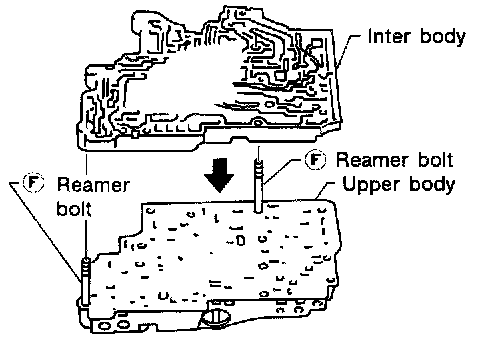
e. Install inter body on upper body using reamer bolts (F) as guides.
- Be careful not to dislocate or drop check balls.
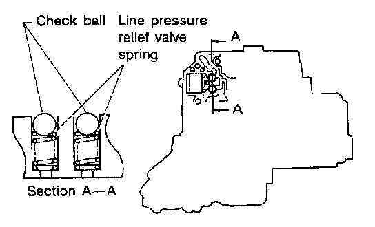
f. Install check balls and relief valve springs in their proper positions in lower body.
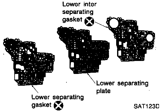
g. Install lower separating gasket, inter separating gasket and lower separating plate in order shown in illustration.
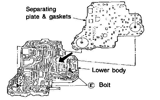
h. Install bolts (E) from bottom of lower body. Using bolts (E) as guides, install separating plate and gaskets as a set.
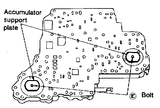
i. Temporarily install support plates on lower body.
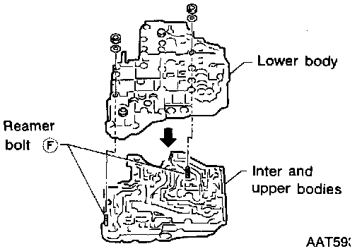
j. Install lower body on inter body using reamer bolts (F) as guides and tighten reamer bolts (F) slightly.
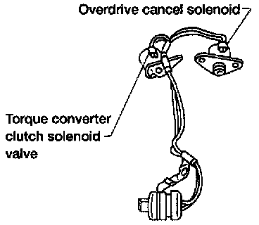
2. Install O-rings to overdrive cancel solenoid valve, torque converter clutch solenoid valve and harness connector.
- Apply ATF to O-rings.
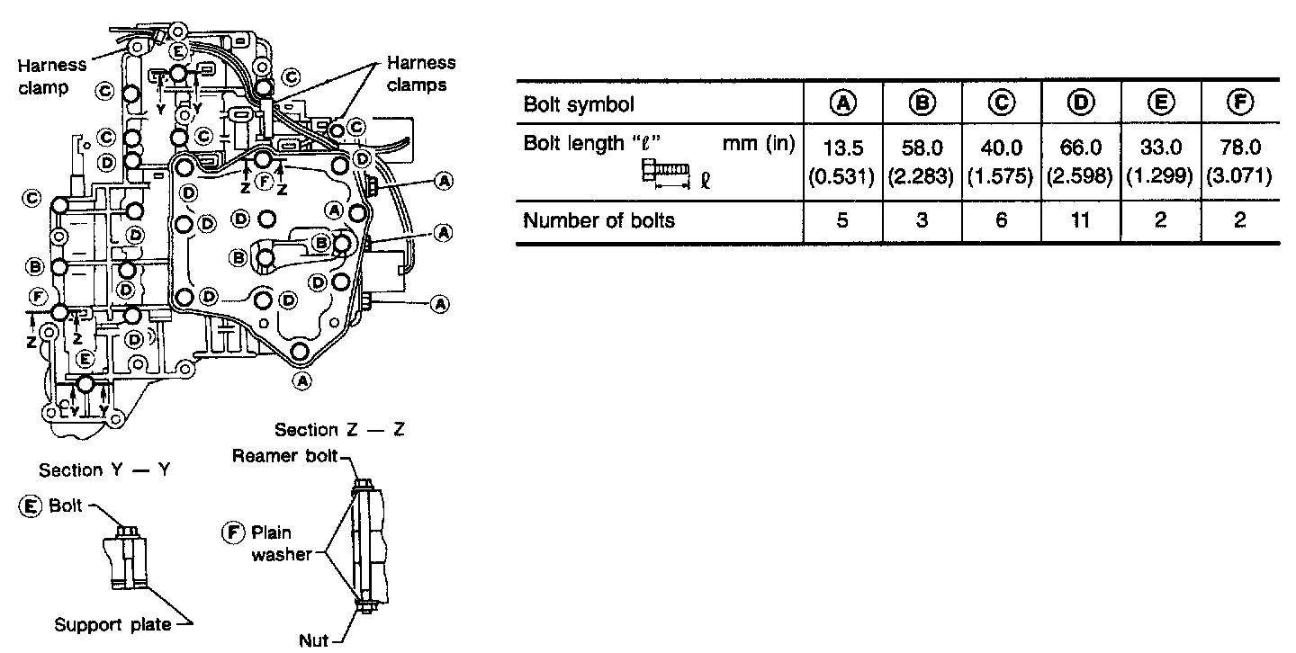
3. Install and tighten bolts as follows.
Bolt length, number and location:
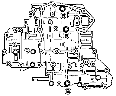
a. Install and tighten bolts @ slightly.
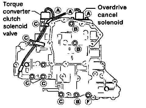
b. Install overdrive cancel solenoid valve and torque converter clutch solenoid valve to lower body.
c. Install and tighten bolts (A) and (C) slightly.
d. Remove both reamer bolts (F) previously installed as guides. Install one reamer bolt (F) (marked in illustration) from lower body side.
e. Tighten bolts (A), (B), (C) and (F) to specified torque.
Torque: 7 - 9 Nm (0.7 - 0.9 kg-m, 61 - 78 inch lbs.)
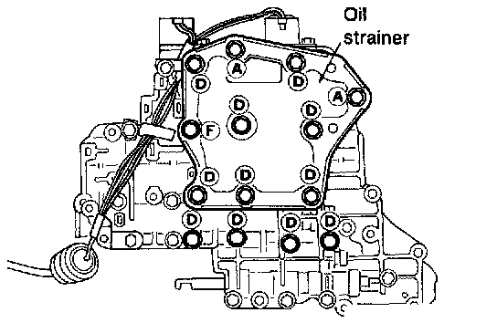
f. Install oil strainer and the other reamer bolt (F) (marked in illustration), then tighten bolts (A), (D) and (F) to specified torque.
Torque: 7 - 9 Nm (0.7 - 0.9 kg-m, 61 - 78 inch lbs.)
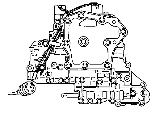
g. Install support plates and tighten bolts @ to specified torque.
Torque: 3.4 - 4.4 Nm (0.35 - 0.45 kg-m, 30.4 - 39.1 inch lbs.)
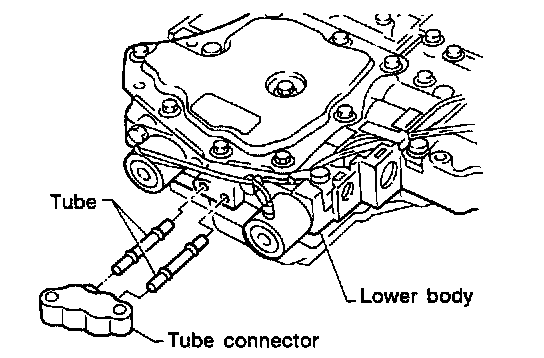
h. Install tube connector and tubes to lower body.
- Install oil circuit side of tube connector face up.
CONTROL VALVE UPPER BODY
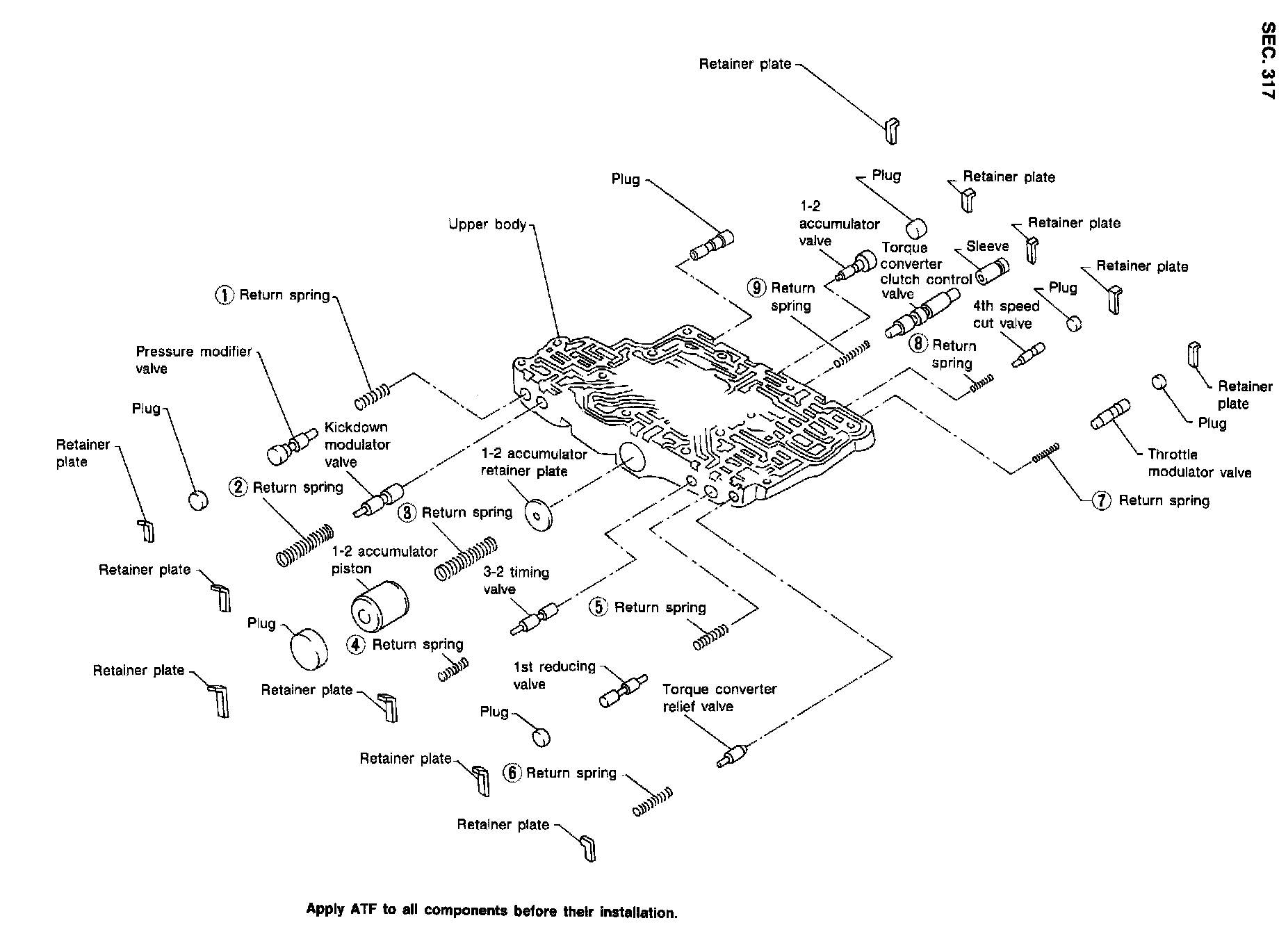
DISASSEMBLY
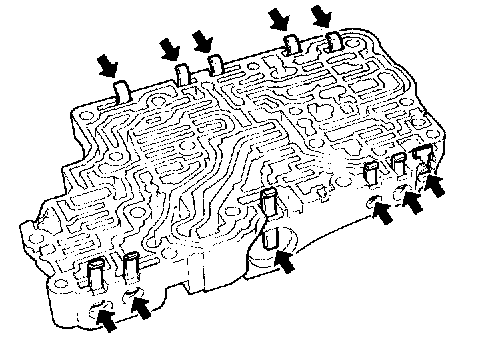
1. Remove valves at retainer plates.
- Do not use a magnetic "hand".
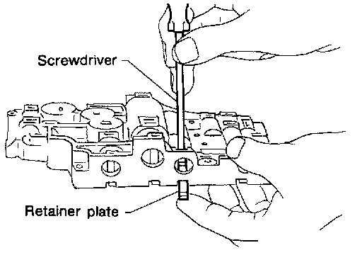
a. Use a screwdriver to remove retainer plates.
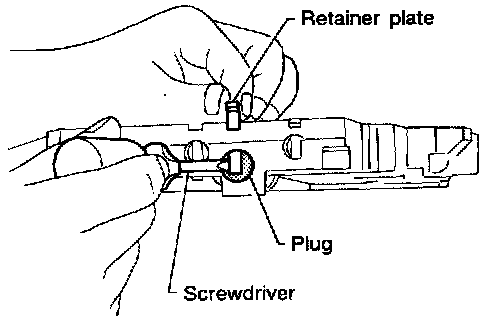
b. Remove retainer plates while holding spring, plugs and sleeves.
- Remove plug slowly to prevent internal parts from jumping out.
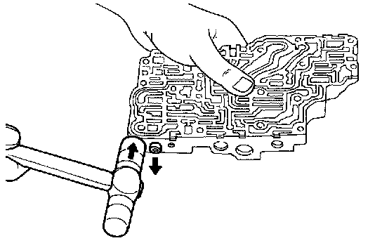
c. Place mating surface of valve face down, and remove internal parts.
- If a valve is hard to remove, place valve body face down and lightly tap it with a soft hammer.
- Be careful not to drop or damage valves and sleeves.
INSPECTION
Valve Spring
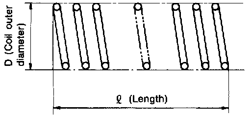
- Measure free length and outer diameter of each valve spring. Also check for damage or deformation.
Inspection standard: Refer to image.
- Replace valve springs if deformed or fatigued.
Control Valves
- Check sliding surfaces of valves, sleeves and plugs.
ASSEMBLY
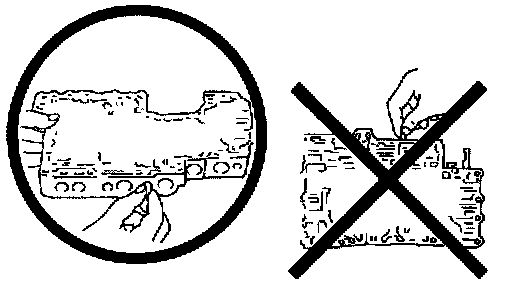
- Lay the control valve body down when installing valves. Do not stand the control valve body on edge.
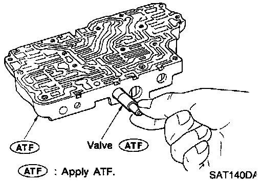
1. Lubricate the control valve body and all valves with ATF. Install control valves by sliding them carefully into their bores.
- Be careful not to scratch or damage valve body.
- Wrap a small screwdriver with vinyl tape and use it to insert the valves into their proper positions.
1-2 Accumulator Valve
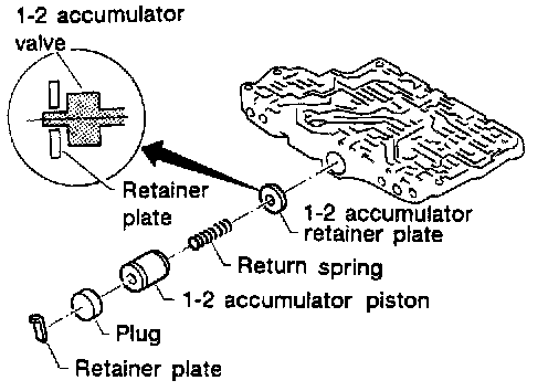
- Install 1-2 accumulator valve. Align 1-2 accumulator retainer plate from opposite side of control valve body.
- Install return spring and 1-2 accumulator piston.
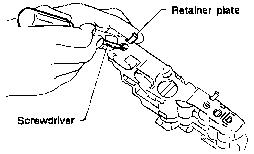
2. Install retainer plates
- While pushing plug or return spring, install retainer plate.
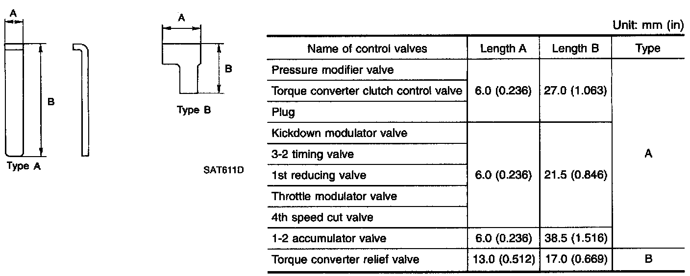
Retainer Plate:
- Install proper retainer plates.
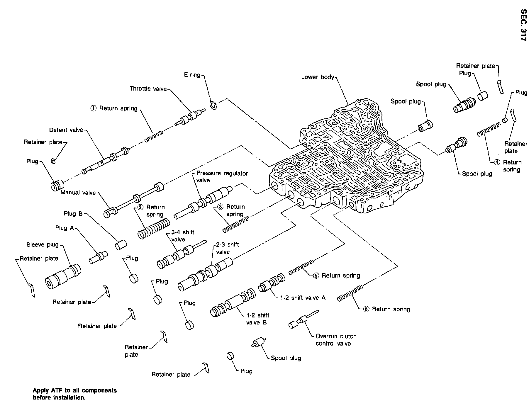
CONTROL VALVE LOWER BODY
DISASSEMBLY
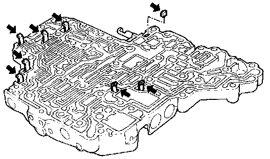
1. Remove valves at retainer plate.
Throttle Valve
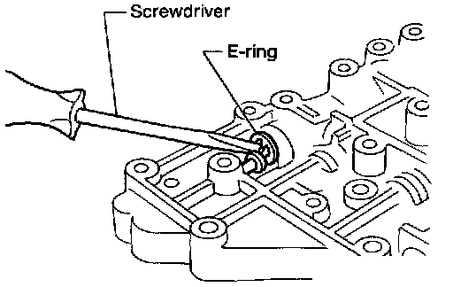
- Remove throttle valve at E-ring.
INSPECTION
Valve Springs
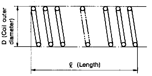
- Check each valve spring for damage or deformation. Also measure free length and outer diameter.
Inspection standard: Refer to image.
- Replace valve springs if deformed or fatigued.
Control Valves
- Check sliding surfaces of control valves, sleeves and plugs for damage.
ASSEMBLY
Throttle Valve
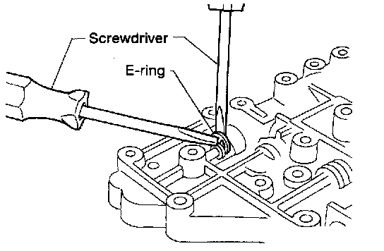
- Insert throttle valve to control valve body and then install E-ring to throttle valve.
Pressure Regulator Valve
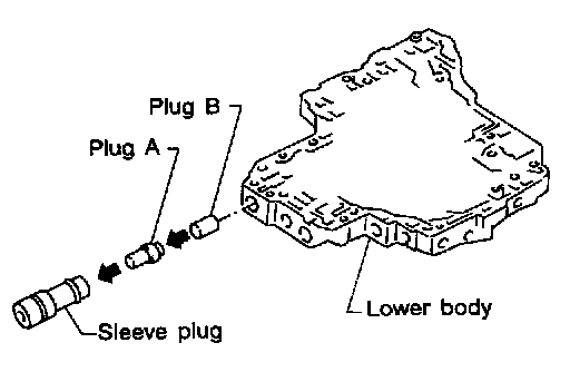
- Install pressure regulator valve after assembling sleeve plug, plug A and plug B.
3-4 Shift Valve And 2-3 Shift Valve
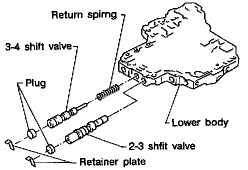
- Install 3-4 shift valve and 2-3 shift valve after fixing plugs to retainer plates on the opposite side.
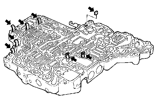
- Install control valves.
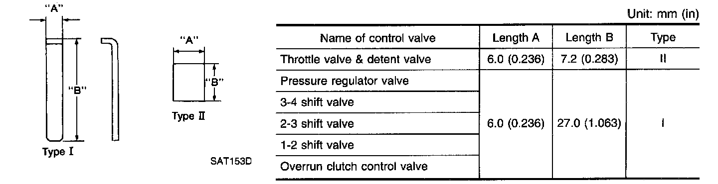
Retainer Plate:
- Install proper retainer plates