Overhaul
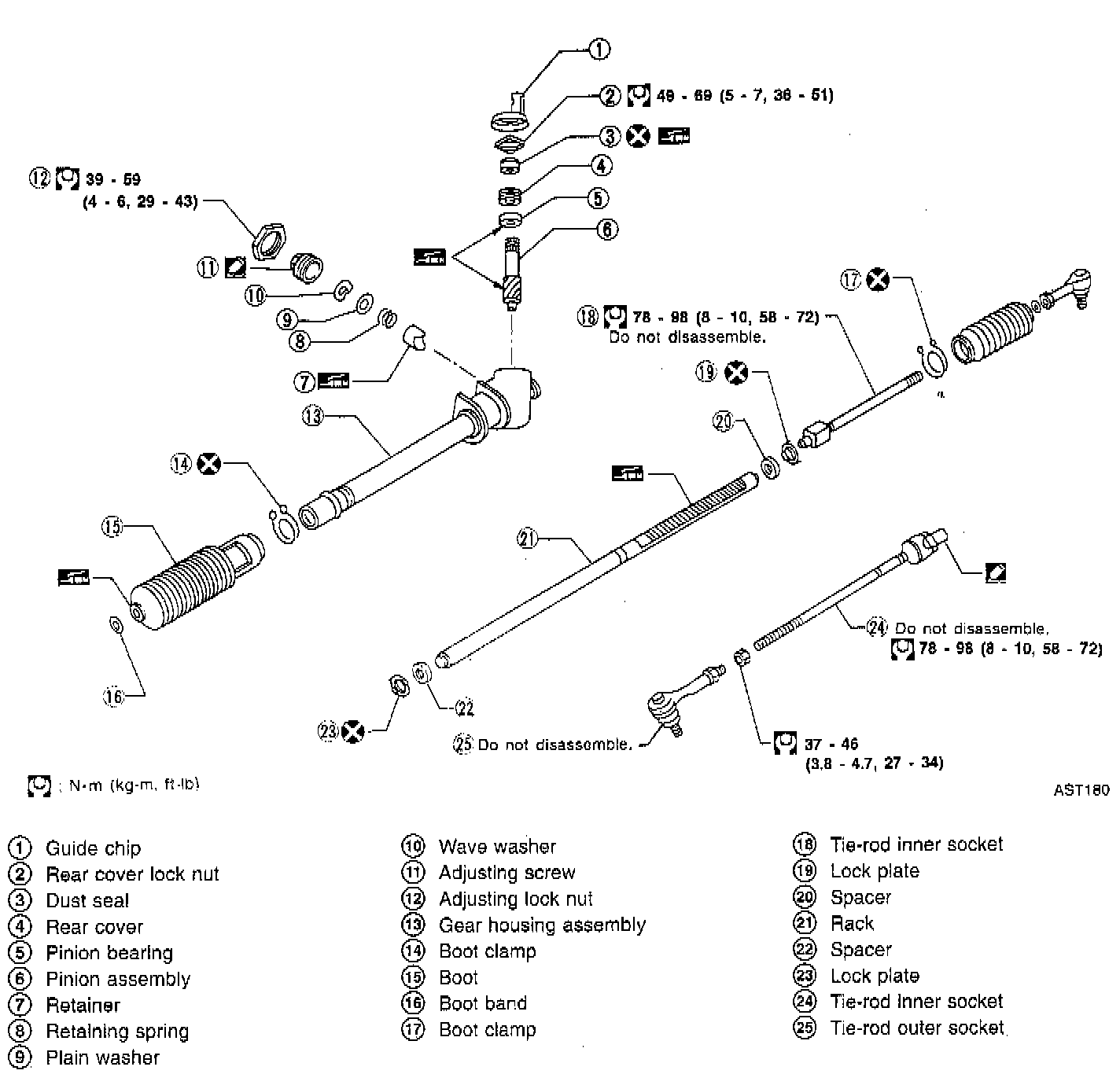
DISASSEMBLY
Refer to the illustrations when servicing.
INSPECTION
Boot
- Check condition of boot. If it is cracked excessively, replace it.
Rack
- Thoroughly examine rack gear. If rack gear is damaged, cracked or worn, replace.
Pinion Assembly
- Thoroughly examine pinion gear. If pinion gear is damaged, cracked or worn, replace.
- Check that all bearings roll freely. Ensure that balls, rollers and races in the bearing assemblies are not cracked, pitted or worn.
- Replace if necessary.
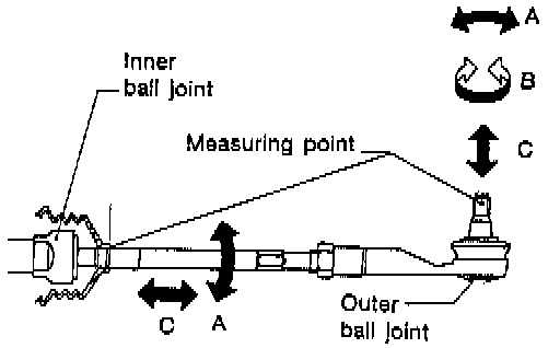
Tie Rod Outer And Inner Sockets
- Check outer and inner ball joints for swinging force "A" and axial end play "C".
- Check outer ball joint for rotating torque "B".
- Check condition of dust cover. If excessively cracked, replace it.
ASSEMBLY AND ADJUSTMENT
Steering Gear
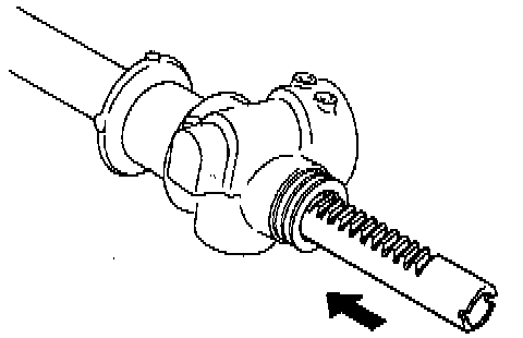
1. Insert rack gear from gear housing side.
2. Set rack gear in neutral position.
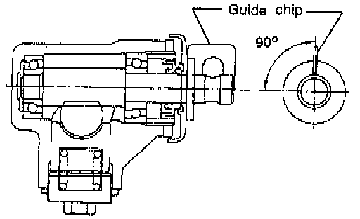
3. Insert pinion assembly, then set guide chip at neutral position as shown in figure. Pinion rack gear should be held in place.
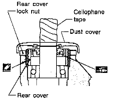
4. Before installing rear cover, apply locking sealant to threaded areas. Do not allow sealant to get into pinion bearing. Apply a coat of multi-purpose grease to sealing lips of dust seal. Install rear cover with end cover socket wrench tool No. KV48102000 (J28822), or equivalent, and secure with lock nut.
CAUTION: Wrap cellophane tape around pinion gear end when installing dust seal.
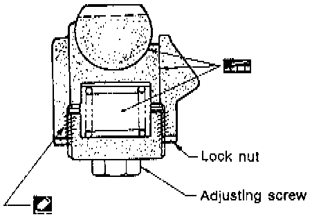
5. Apply a coat of locking sealant to threaded areas of retainer cover. Insert retainer, spring, plain washer and wave washer. Then, install adjusting screw.
6. Adjust pinion rotating torque as follows:
a. Set gears to neutral position.
b. Loosen lock nut.
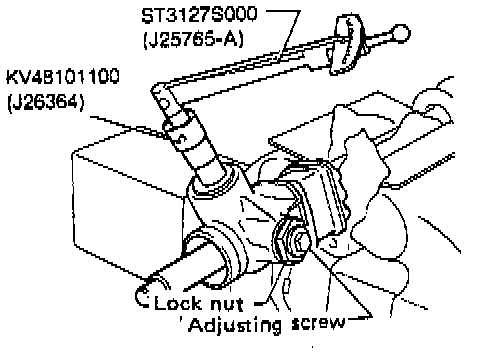
c. Tighten adjusting screw to a torque of 9.8 Nm (87 inch lbs.).
d. Loosen adjusting screw and retighten it to a torque of 9.8 Nm (87 inch lbs.).
e. Loosen adjusting screw within 60° until specified pinion torque is obtained. Ensure that pinion-to-rack play is less than 0.1 mm (0.004 inch) when 15 Nm (11 ft. lbs.) torque is applied to pinion.
f. Prevent adjusting nut from rotating and tighten lock nut to specified torque 39 - 59 Nm (29 - 43 ft. lbs.), while holding adjusting screw in place.
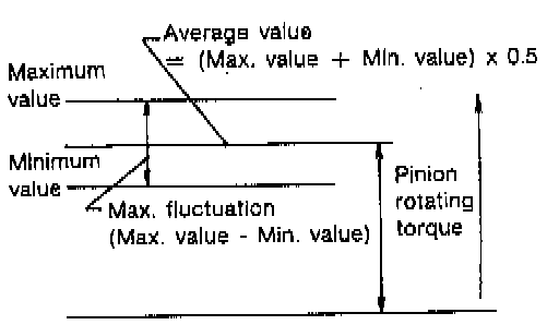
g. While slowly rotating pinion in the ±100° range from neutral position, make sure its rotating torque is within the specifications.
Within ± 100° from the neutral position:
Average rotating torque: 0.7 - 1.2 Nm (6.1 - 10.4 inch lbs.)
Maximum torque deviation: 0.3 Nm (2.6 inch lbs.)
Except for above measuring range:
Maximum rotating torque: 1.5 Nm (13 inch lbs.)
Maximum force deviation: 0.5 Nm (4.3 inch lbs.)
h. If pinion rotating torque is not within the specifications, readjust.
NOTE:
^ If pinion rotating torque is outside the specifications after adjustment has been made, replace retainer spring.
^ If pinion rotating torque is still out of specifications after replacing retainer spring, replace gear assembly.
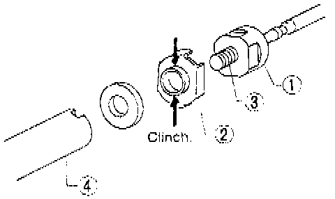
7. Install new lock plate as follows:
a. Attach lock plate No. 2 to side rod inner socket No. 1.
b. Apply locking sealant to inner socket threads No. 3. Screw inner socket into rack No. 4 and tighten to specified torque.
c. Clinch two places of lock plate at rack's groove.
CAUTION: To prevent scratching the boot, remove burrs from lock plate.
Tie-rod and Boot
1. Install boot on tie rod inner socket.
2. Apply locking sealant to threaded portion of inner socket. Install tie rod inner socket to rack end together with new lock plate.
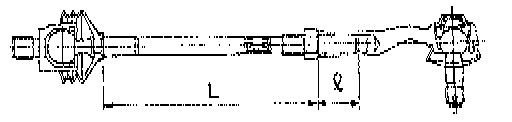
3. Install lock nut and outer socket to inner socket. Adjust tie rod length "L" and tighten lock nut. Tie rod length "L": 187 mm (7.36 inch)
Screwed length "l": 32 mm (1.26 inch) or more.
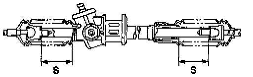
4. Measure rack stroke.
Rack stroke: 69 - 71 mm (2.72 - 2.80 inch)
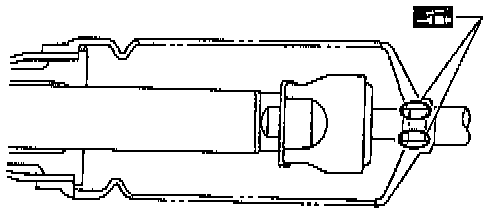
5. Before installing boot, coat the contact surfaces between boot and tie rod with grease.
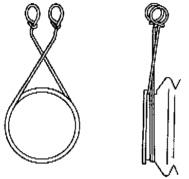
6. To install boot clamps, wrap boot clamp around boot groove twice. Use a screwdriver to tighten clamps. Twist rings at both ends 4 - 4.5 turns while pulling them with a force of approximately 98 N (22 lbs.).
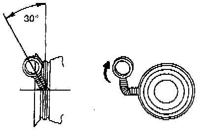
CAUTION: Do not cross wire on boot. Bend twisted end of boot clamp as shown. (This will prevent interference with other parts.)