Rear
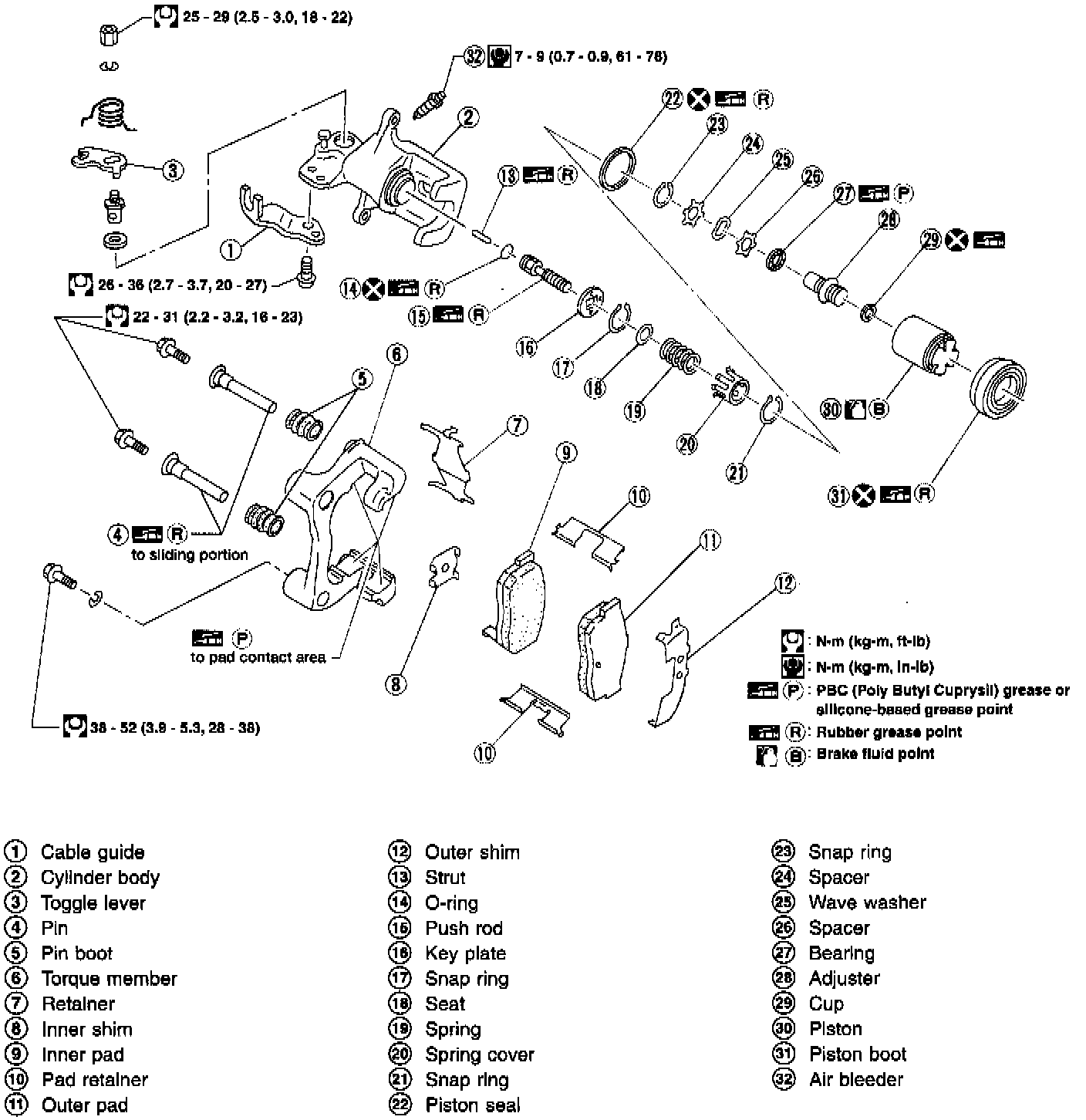
REMOVAL
WARNING: Clean brake pads with a vacuum dust collector to minimize the hazard of airborne particles or other materials.
Rear Disc Fasteners:
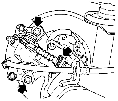
1. Remove parking brake cable lock plate.
2. Remove torque member fixing bolts and connecting bolt.
NOTE: It is not necessary to remove connecting bolt except for disassembly or replacement of caliper assembly. In this case, suspend caliper assembly with wire so as not to stretch brake hose.
DISASSEMBLY
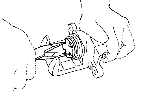
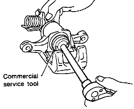
1. Remove piston by turning it counterclockwise with suitable long nose pliers or commercial service tool.
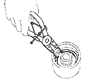
2. Remove snap ring from piston with suitable pliers and remove adjusting nut.
3. Disassemble cylinder body.
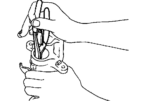
a. Pry off snap ring with suitable pliers, then remove spring cover, spring and seat.
b. Remove snap ring, then remove key plate, push rod and strut.
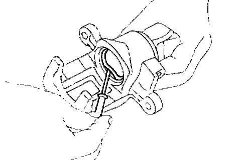
c. Remove piston seal. Be careful not to damage cylinder body.
Return Spring, Toggle Lever And Cable Guide Removal:
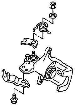
4. Remove return spring, toggle lever and cable guide.
INSPECTION
CAUTION: Use brake fluid to clean cylinder. Never use mineral oil.
Cylinder Body
- Check inside surface of cylinder for scoring, rust, wear, damage or presence of foreign objects. If any of the above conditions are observed, replace cylinder body.
- Minor damage from rust or foreign objects may be eliminated by polishing surface with a fine emery paper. Replace cylinder body if necessary.
Torque Member
- Check for wear, cracks or other damage. Replace if necessary.
Piston
CAUTION: Piston sliding surface is plated. Do not polish with emery paper even if rust or foreign objects are stuck to sliding surface.
- Check piston for score, rust, wear, damage or presence of foreign objects. Replace if any of the above conditions are observed.
Slide Pin, Pin Bolt, And Pin Boot
- Check for wear, cracks or other damage.
Replace if any of the above conditions are observed.
Rotor
Rubbing Surface
- Check rotor for roughness, cracks or chips.
Runout
1. Secure rotor to wheel hub with at least two nuts (M12 x 1.25).
Checking Rotor Runout:
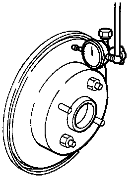
2. Check runout using a dial indicator.
Make sure that wheel bearing axial end play is within the specifications before measuring.
3. Change relative positions of rotor and wheel hub so that runout is minimized.
Maximum runout: 0.07 mm (0.0028 inch)
Thickness
- Replace rotor if any of the following do not meet the specifications.
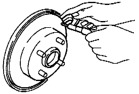
Rotor repair limit:
Minimum thickness: 6.0 mm (0.236 inch)
Thickness variation (at least 8 positions): Maximum 0.02 mm (0.0008 inch)
ASSEMBLY
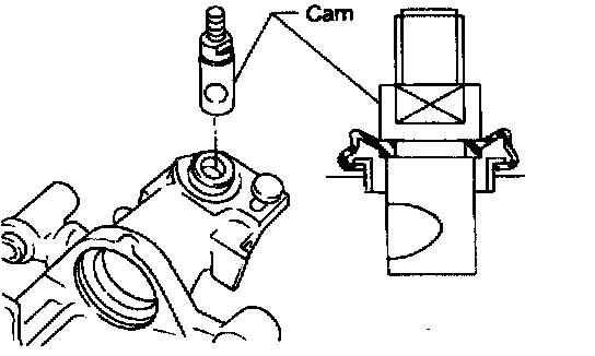
1. Insert cam with depression facing towards open end of cylinder.
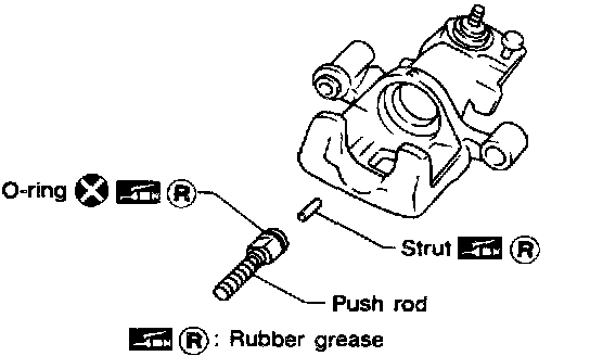
2. Generously apply rubber grease to strut and push rod to make insertion easy.
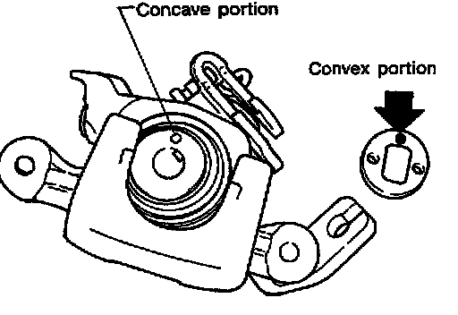
3. Match protrusion on key plate with depression in cylinder.
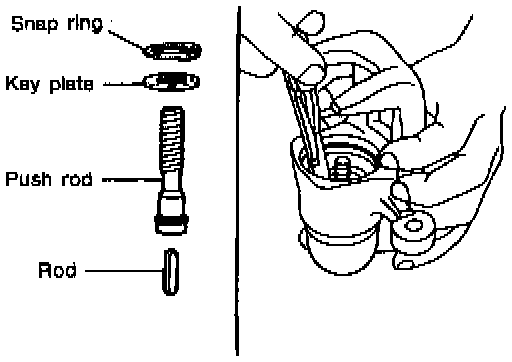
4. Install snap ring with a suitable tool.
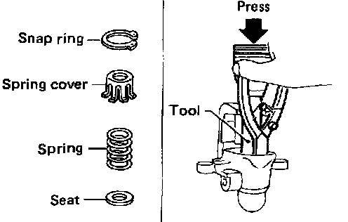
5. Install seat, spring, spring cover and snap ring while depressing with a suitable tool.
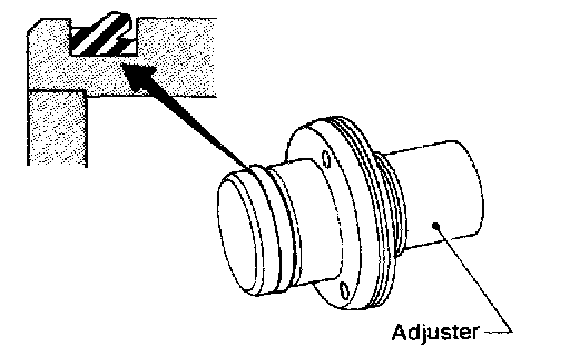
6. Install adjuster in the specified direction.
Piston Component Installation:
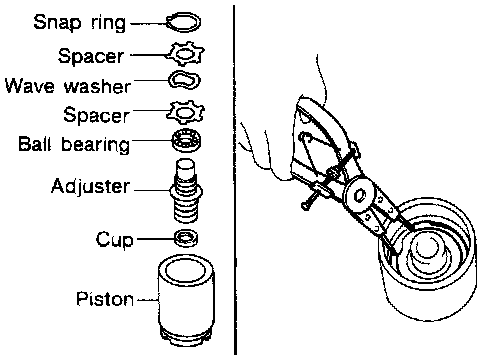
7. Install cup, adjuster, bearing, spacers, washer and snap ring with a suitable tool.
8. Insert piston seal into groove on cylinder body.
9. With piston boot fitted to piston, insert piston boot into groove on cylinder body and fit piston by turning it clockwise with long nose pliers, or suitable tool.
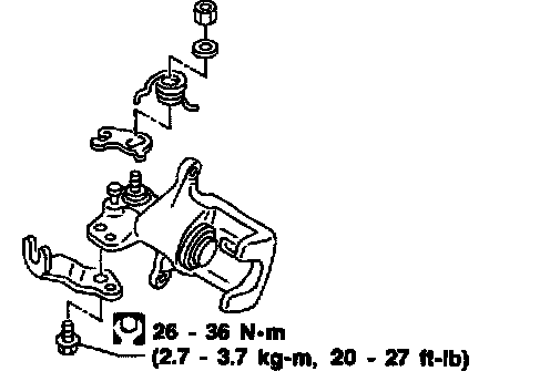
10. Fit toggle lever, return spring and cable guide.
INSTALLATION
CAUTION:
- Refill with new brake fluid DOT 3.
- Never reuse drained brake fluid.
1. Install caliper assembly.
2. Install brake hose to caliper securely.
3. Install all parts and secure all bolts.
4. Bleed air. Refer to Brake Bleeding Procedure.