Overhaul
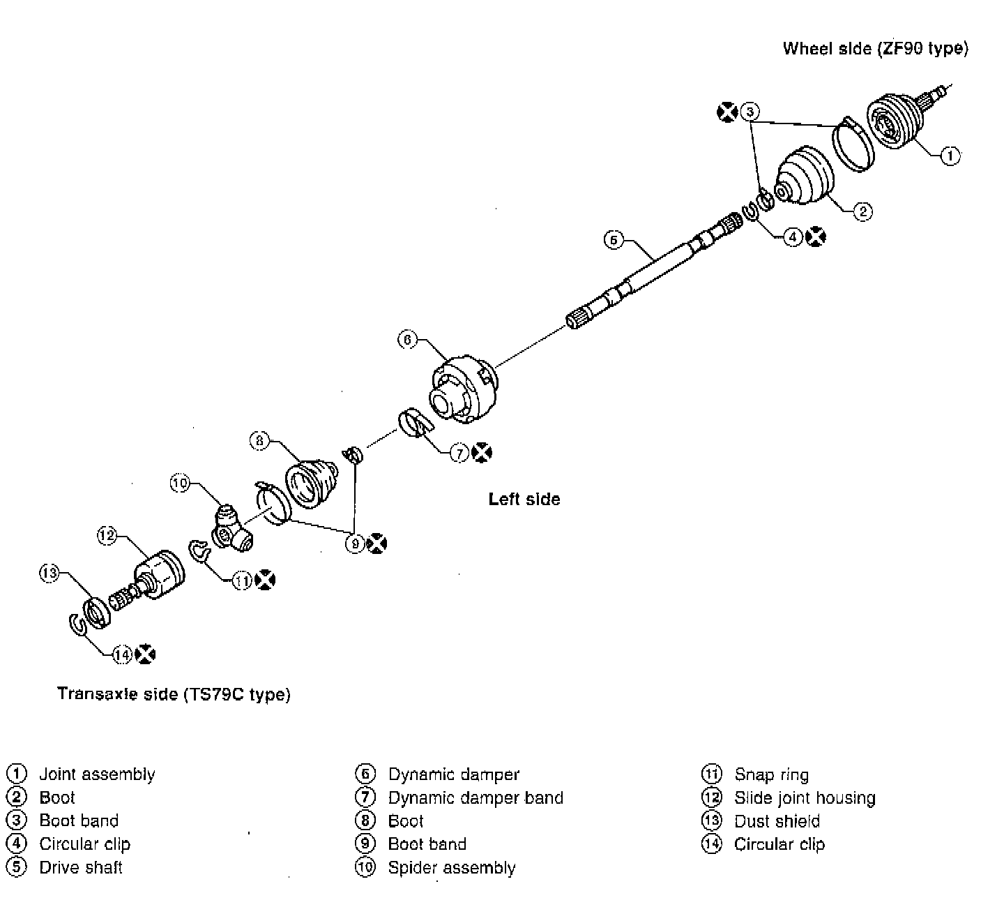
DISASSEMBLY
Transaxle Side
1. Remove boot bands.
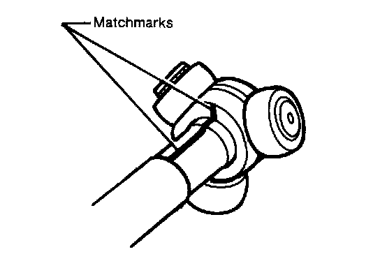
2. Put matching marks on slide joint housing and drive shaft before separating joint assembly.
3. Put matching marks on spider assembly and drive shaft.
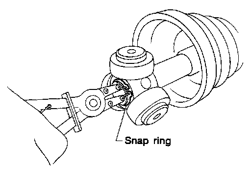
4. Remove snap ring, then remove spider assembly.
CAUTION: Do not disassemble spider assembly and cover drive shaft serration with tape to prevent damage to the boot.
5. Draw out boot.
Wheel Side
1. Before separating joint assembly, put matching marks or drive shaft and joint assembly.
CAUTION: The joint on the wheel side cannot be disassembled.
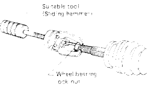
2. Separate joint assembly with a suitable tool.
CAUTION: Be careful not to damage threads on drive shaft.
3. Remove boot bands.
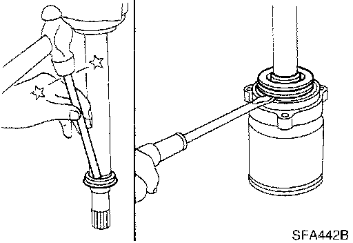
Support Bearing
1. Remove dust shield.
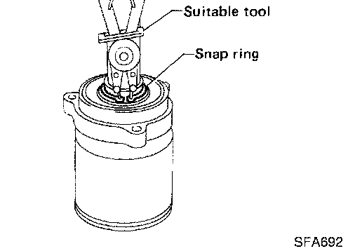
2. Remove snap ring.
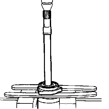
3. Press support bearing assembly off of drive shaft.
4. Remove snap ring.
5. Remove dust shield.
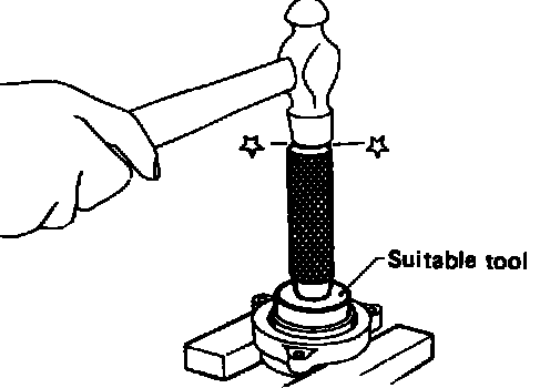
6. Separate support bearing from retainer.
INSPECTION
General
^ Thoroughly clean all parts in cleaning solvent, then dry with compressed air. Check parts for evidence of deformation and other damage.
Drive Shaft
^ Replace drive shaft if it is twisted or cracked.
Boot
^ Check boot for fatigue, cracks and wear. Replace boot with new boot bands.
Joint Assembly (Transaxle Side)
^ Check spider assembly for needle bearing and washer damage. Replace if necessary.
^ Check roller surfaces for scratches, wear and other damage. Replace if necessary.
^ Check serration for deformation. Replace if necessary.
^ Check slide joint housing for any damage. Replace if necessary.
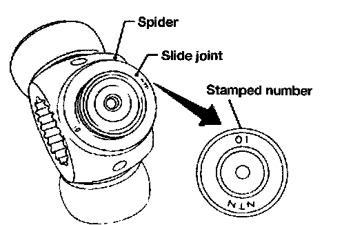
^ When replacing only spider assembly, select a new spider assembly from among those listed in table shown. Ensure that the number stamped on slide joint is the same as that stamped on new part. The housing alone cannot be replaced. It must be replaced together with solder assembly.
Stamped Number/Part No.
01/ 39720-61 E01
02/ 39720-61 E02
03/ 39720-61 E03
04/ 39720-61 E04
05/ 39720-61 E05
06/ 39720-61 E06
07/ 39720-61 E07
Joint Assembly (Wheel Side)
^ Replace joint assembly if it is deformed or damaged.
Support Bearing
^ Make sure support bearing rolls freely and is free from noise, cracks, pitting and wear.
Support Bearing Bracket
^ Check support bearing bracket for cracks with a magnetic exploration or dyeing test.
ASSEMBLY
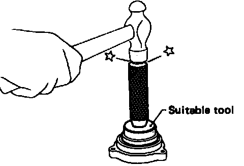
Support Bearing
1. Install bearing into retainer.
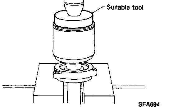
2. Install dust shield.
3. Install snap ring.
4. Press drive shaft into bearing.
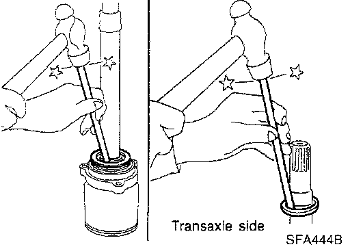
5. Install snap ring.
6. Install new dust shield.
Wheel Side
1. Install boot and new small boot band on drive shaft.
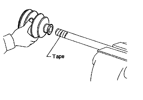
CAUTION: Cover drive shaft serration with tape to prevent damage to boot during installation.
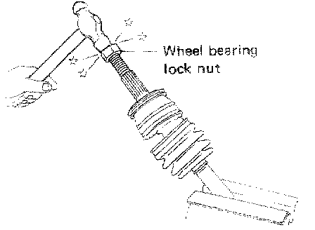
2. Set joint assembly onto drive shaft by lightly tapping it. Ensure that marks which were made during disassembly are properly aligned.
3. Pack drive shaft with 115 - 125 grams (4.06 - 4.41 oz) of grease.
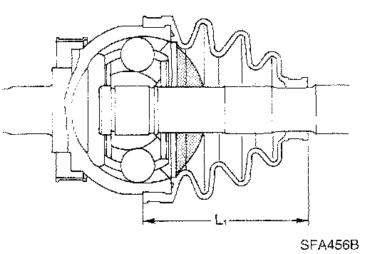
4. Make sure that boot is properly installed on the drive shaft groove. Set boot so that it does not swell and deform when its length is "L1". Length "L1": 96 - 98 mm (3.78 - 3.86 inch)
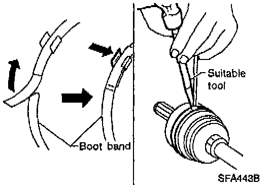
5. Lock new larger and smaller boot bands securely with a suitable tool.
Dynamic Damper
1. Use a new damper band when reinstalling.
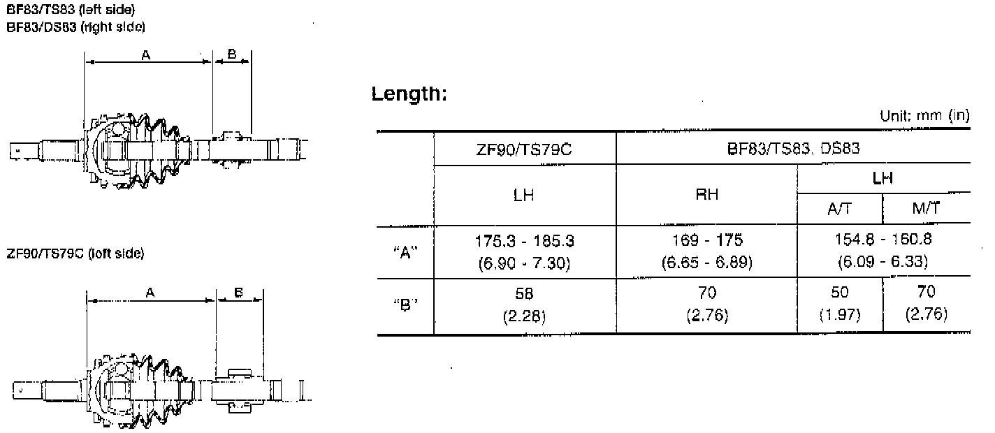
2. Install dynamic damper from stationary joint side while holding it securely:
Transaxle Side
1. Install boot and new small boot band on drive shaft.
CAUTION: Cover drive shaft serration with tape to prevent damage to boot during installation.
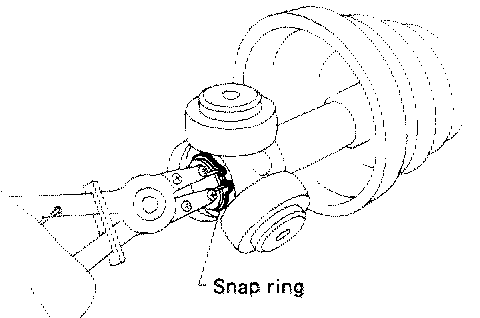
2. Install spider assembly securely, making sure the matching marks which were made during disassembly are properly aligned.
3. Install new snap ring.
4. Pack drive shaft with 155 - 165 grams (5.47 - 5.82 ounce) of grease.
5. Install slide joint housing.
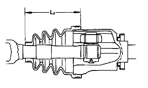
6. Set boot so that it does not swell and deform when its length is "L2". Length "L2": 101.5 - 103.5 mm (4.00 - 4.07 inch)
NOTE: Make sure that the boot is properly installed on the drive shaft groove.
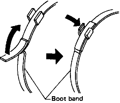
7. Lock new larger and smaller boot bands securely with suitable tool.
NOTE:
^ After drive shaft has been assembled, ensure that it moves smoothly over its entire range without binding.
^ Use Nissan Genuine Grease or equivalent after every overhaul.