Disassembly and Assembly
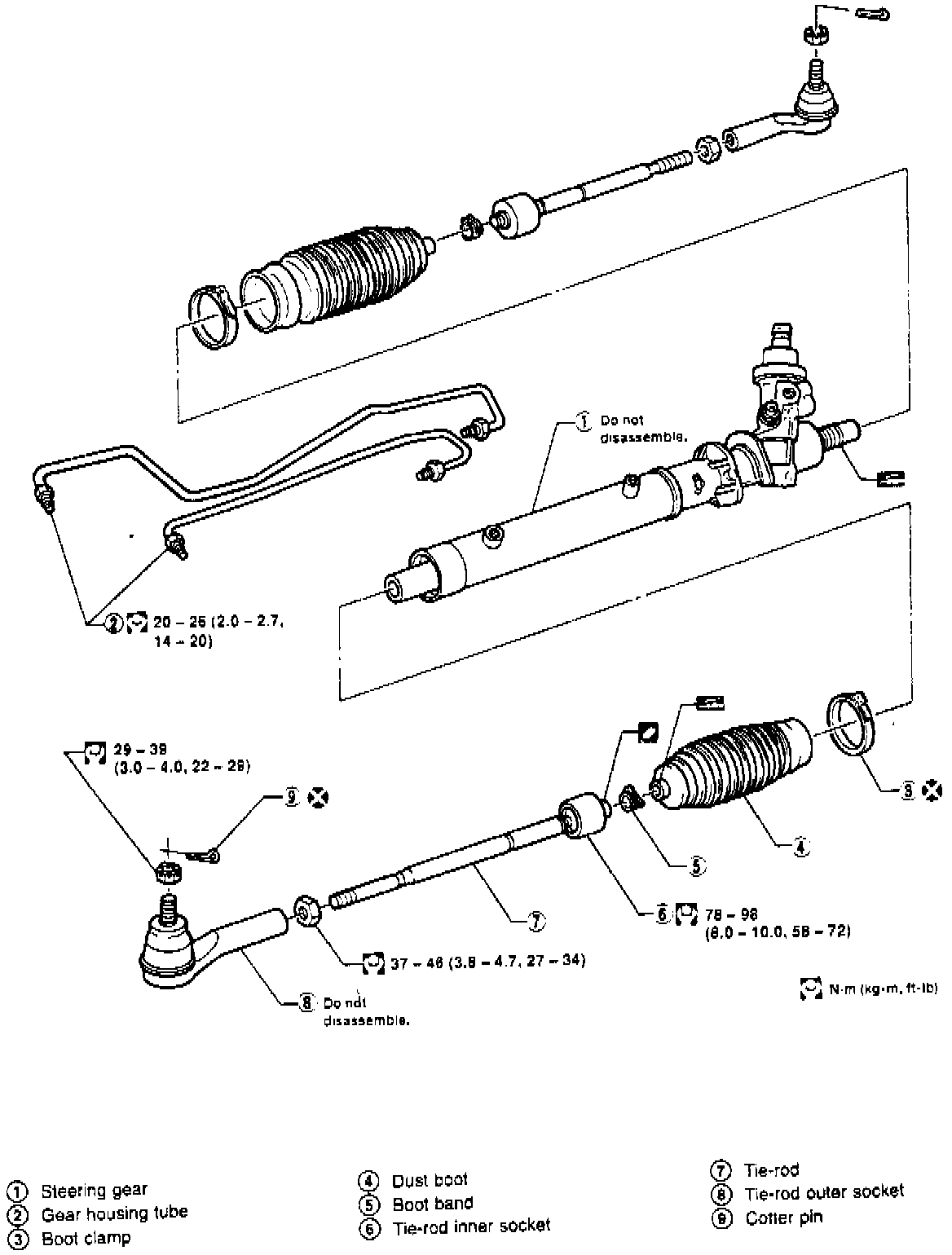
NOTE: When performing repair procedures on this power steering rack, use a vise with soft jaws to hold the steering gear housing. Do not grip the cylinder in a vise.Fig. 17 Disassembled View Of Rack & Pinion Type Power Steering Gear:
DISASSEMBLE
1. Disconnect gear housing tube and drain fluid, Fig. 17.
2. Measure pinion rotating torque as described under " Adjustment.
3. Remove tie-rod outer sockets and boots.
4. Remove tie-rod inner sockets.
5. Do not attempt to disassemble gear housing or cylinder.
INSPECTION
Clean all parts in cleaning solvent or Type F automatic transmission fluid and blow dry with compressed air.
1. Check boot for cracks.
Fig. 18 Tie-rod Ball Joint Swinging Force Inspection:
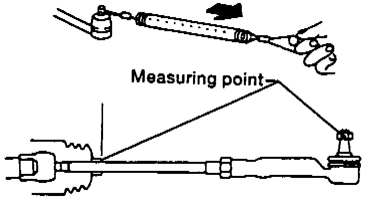
2. Check tie-rod ball joint swinging force as shown in Fig. 18. If outer ball joint swing force is not within 0.4-30.9 inch lbs; replace tie-rod end. If inner ball joint swing force is not within 0.04-4.41 inch lbs; replace tie-rod end.
Fig. 19 Tie-rod End Rotating Torque Inspection:
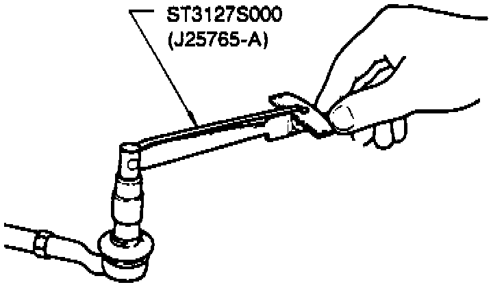
3. Check tie-rod end rotating torque as shown in Fig. 19. If rotating torque is not within 1.3-5.5 inch lbs; replace tie-rod end.
ASSEMBLE
1. Install tie-rod end inner and outer sockets.
2. Tighten outer socket locknut to specifications.
Fig. 20 Rack Stroke Measurement:
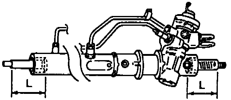
3. Measure rack stroke as shown in Fig. 20, rack stroke should be 2.83 inches. Adjust stroke as necessary.
4. To prevent interference with other parts. Install boot clamps so they are behind the gear housing when it is attached to the vehicle.
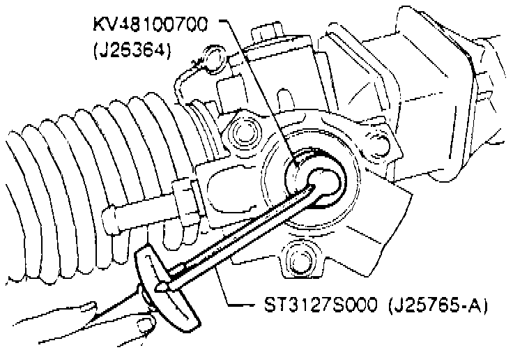
Fig. 21 Pinion Rotating Torque Measurement:
ADJUSTMENT
1. Measure pinion rotating torque as shown, Fig. 21.
2. Pinion rotating torque should be 4.3-12.5 inch lbs. with a maximum deviation of 3.5 inch lbs. If torque is not within specifications, replace steering rack.
3. Check rack sliding force as follows:
a. Disconnect tie-rod ends from knuckle assembly.
b. Start engine and bleed air completely.
c. Disconnect steering column lower joint from gear.
d. Keep engine at idle speed and make sure steering fluid has reached normal operating temperature.
Fig. 22 Rack Sliding Force Measurement:
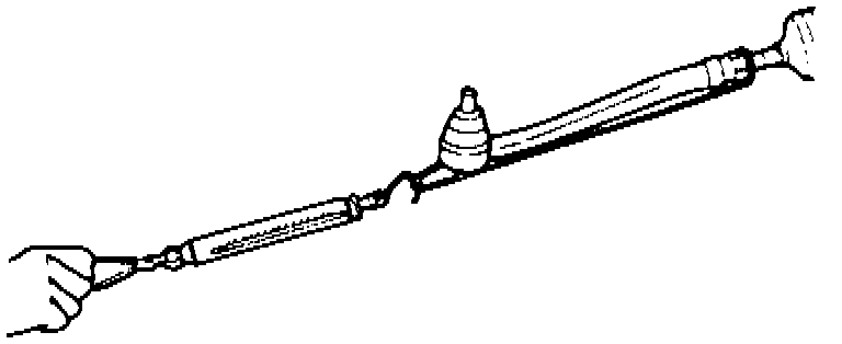
e. While pulling tie-rod end slowly in the (+/- 2.56 inch) range from the neutral position, ensure sliding force is less than 60 lbs., Fig. 22.
f. Check rack outside of (+/- 2.56 inch) range, sliding force should not be above 13 lbs.
g. If sliding force is not within specifications, repeat adjustment procedure.