Disassembly, Inspection and Assembly
Fig. 7 Exploded View Of Timing Chain & Cylinder Head Components (part 1 Of 2).:
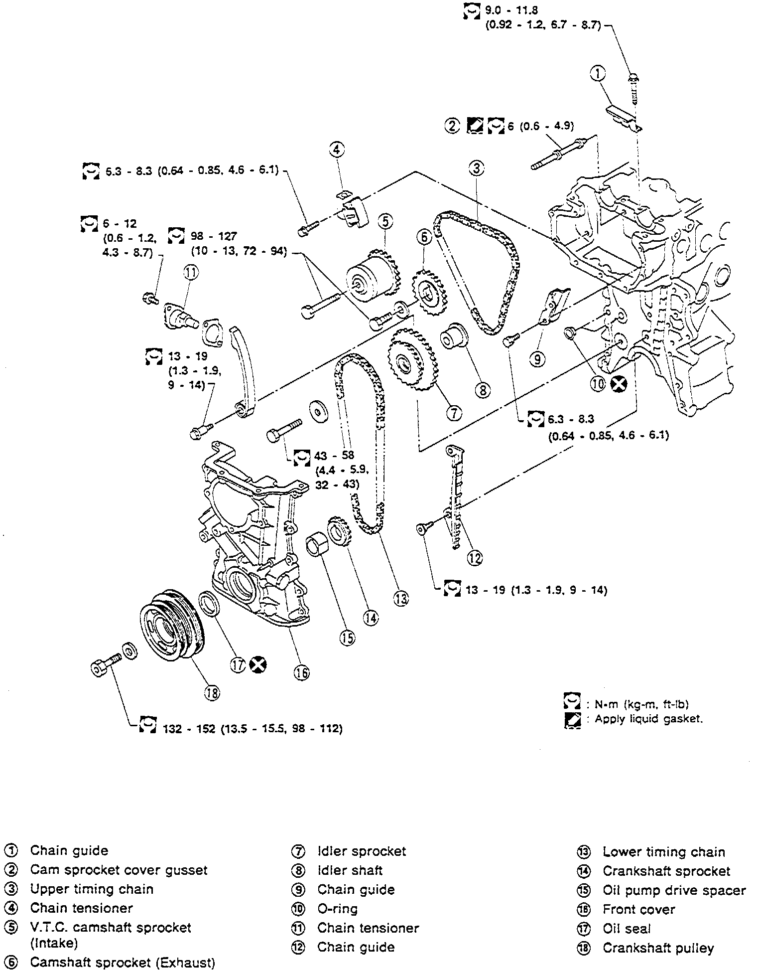
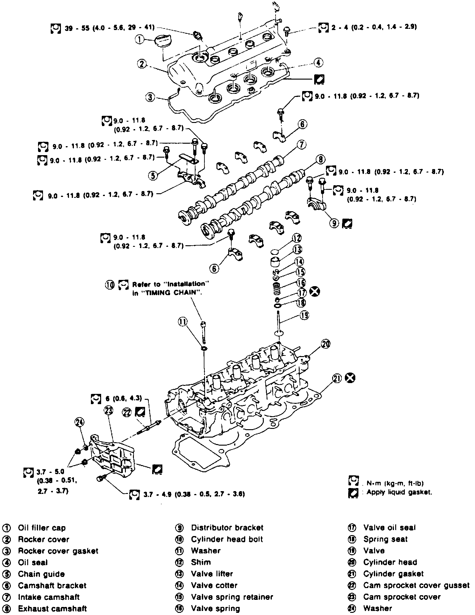
Fig. 7 Exploded View Of Timing Chain & Cylinder Head Components (part 2 Of 2).:
DISASSEMBLY
Refer to Fig. 7 when performing the following procedure.
1. Remove intake and exhaust manifolds from cylinder head. Refer to Intake Manifold and Exhaust System for removal procedure.
2. Remove valve components using valve spring compression and attachment tool Nos. KV10116200 (J26339-A) and KV10115900 (J26336-20), or equivalents.
3. Remove valve oil seals using seal puller tool No. KV10107902 (J38959), or equivalent.
ASSEMBLY
Refer to Fig. 7 when performing the following procedure.
1. Install valve oil seals using seal drift tool No. KV10115600 (J38958), or equivalent.
2. Install valve components using valve spring compression and attachment tool Nos. KV10116200 (J26339-A) and KV10115900 (J26336-20), or equivalents. When installing valve springs, ensure narrow pitch of spring is pointed toward cylinder head.
3. Install intake and exhaust manifolds to cylinder head. Refer to Intake Manifold and Exhaust System for procedures.