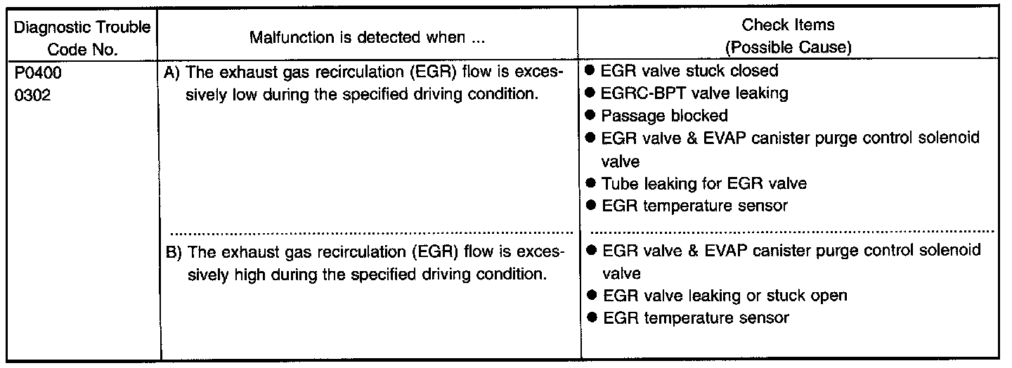
P0400

DESCRIPTION
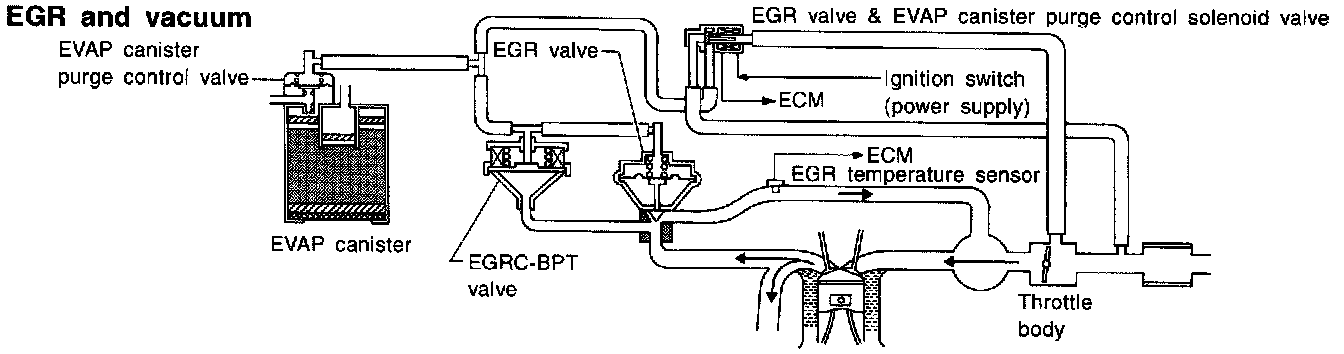
This system cuts and controls vacuum applied to EGR valve and EVAP canister to suit engine operating conditions. This cut-and-control operation is accomplished through the ECM and the EGR valve & EVAP canister purge control solenoid valve. When the ECM detects any of the following conditions, current flows through the solenoid valve. This causes the port vacuum to be discharged into the atmosphere. The EGR valve and EVAP canister remain closed.
- Low engine coolant temperature
- Engine starting
- High-speed engine operation
- Engine idling
- Excessively high engine coolant temperature
- Mass air flow sensor malfunction
COMPONENT DESCRIPTION
Exhaust Gas Recirculation (EGR) Valve
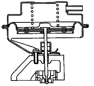
The EGR valve controls the amount of exhaust gas routed to the intake manifold. Vacuum is applied to the EGR valve in response to throttle valve opening. The vacuum controls the movement of a taper valve connected to the vacuum diaphragm in the EGR valve.
EGR Valve & EVAP Canister Purge Control Solenoid Valve
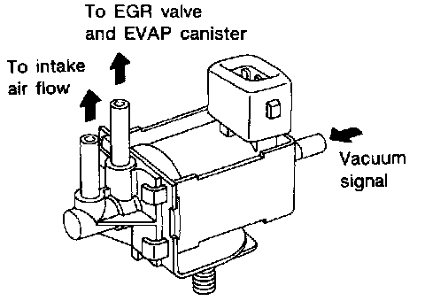
The EGR valve & EVAP canister purge control solenoid valve responds to signals from the ECM. When the ECM sends an ON (ground) signal, the coil in the solenoid valve is energized. A plunger will then move to cut the vacuum signal (from the throttle body to the EGR valve & EVAP canister purge control valve).
When the ECM sends an OFF signal, the vacuum signal passes through the solenoid valve. The signal then reaches the EGR valve and EVAP canister.
ON-BOARD DIAGNOSIS LOGIC
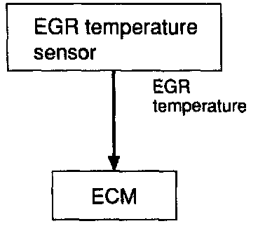
If the absence of EGR flow is detected by EGR temperature sensor under the condition that calls for EGR, a low-flow malfunction is diagnosed.
If EGR temperature sensor detects EGR flow under the condition that does not call for EGR, a high-flow malfunction is diagnosed.
DIAGNOSTIC TROUBLE CODE CONFIRMATION PROCEDURE
OVERALL FUNCTION CHECK
Use this procedure to check the overall EGR function. During this check, a DTC might not be confirmed.
Before starting with the following procedure, check the engine coolant temperature of the freeze frame data with CONSULT or Generic Scan Tool.
If the engine coolant temperature is higher than or equal to 71°C (160°F), perform only "Procedure for malfunction A".
If the engine coolant temperature is lower than 71°C (160°F), perform both "Procedure for malfunction A" and "Procedure for malfunction B".
Procedure for malfunction A
1) Start engine and warm it up sufficiently.
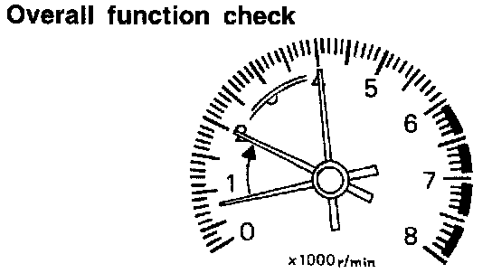
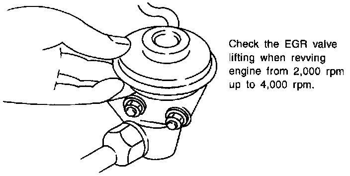
2) Check the EGR valve lifting when revving from 2,000 rpm up to 4,000 rpm under no load.
EGR valve should lift up and down without sticking.
If EGR valve does not lift up and down, try again with either of the following methods:
WITH CONSULT
- Select "EGRC SOLENOID VALVE" in "ACTIVE TEST" mode with CONSULT and turn the solenoid valve "OFF".
WITH NO TOOLS
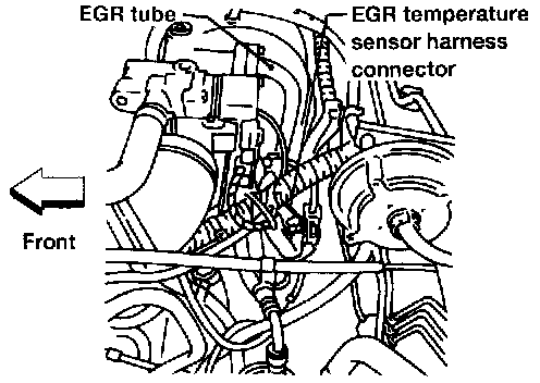
- Disconnect EGR valve & EVAP canister purge control solenoid valve harness connector.
(The DTC for EGR valve & EVAP canister purge control solenoid valve will be displayed, however, ignore it.)
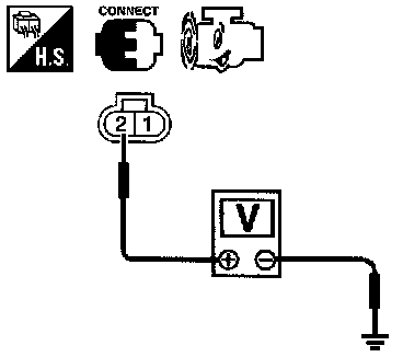
3) Check voltage between EGR temperature sensor harness connector terminal (2) and ground at idle speed. Less than 4.5V should exist.
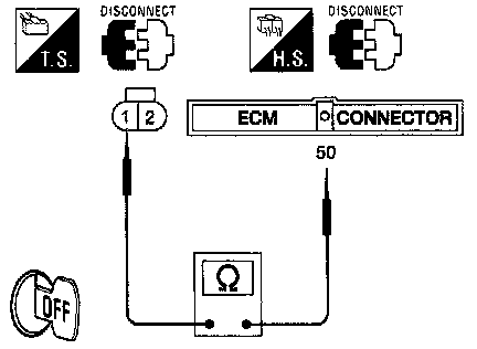
4) Turn ignition switch "OFF".
Check harness continuity between EGR temperature sensor harness connector terminal (1) and ECM terminal (50). Continuity should exist.
5) Perform "COMPONENT INSPECTION", "EGR temperature sensor".
Procedure for malfunction B
WITH CONSULT
1) Start engine.
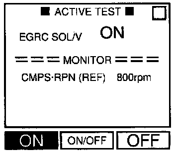
2) Select "EGRC SOLENOID VALVE" in "ACTIVE TEST" mode with CONSULT and turn the solenoid valve "ON".
3) Check for the EGR valve lifting when revving from 2,000 rpm up to 4,000 rpm under no load.
EGR valve should be closed and should not lift up.
OR
WITH GST
1) Confirm the engine coolant temperature is lower than 71°C (160°F) in "Mode 1" with generic scan tool.
Perform the following steps before its temperature becomes higher than 71°C (160°F).
2) Start engine.
3) Check for the EGR valve lifting when revving from 2,000 rpm up to 4,000 rpm under no load.
EGR valve should be closed and should not lift up.
OR
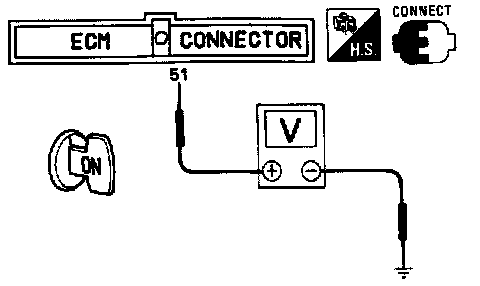
WITH NO TOOLS
1) Confirm the voltage between ECM terminal (51) and ground is higher than 1.48V.
Perform the following steps before the voltage becomes lower than 1.48V.
2) Start engine.
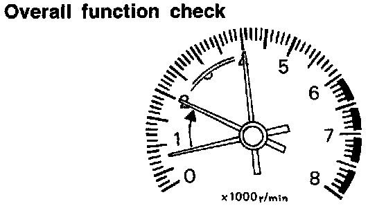
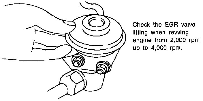
3) Check for the EGR valve lifting when revving from 2,000 rpm up to 4,000 rpm under no load.
EGR valve should be closed and should not lift up.
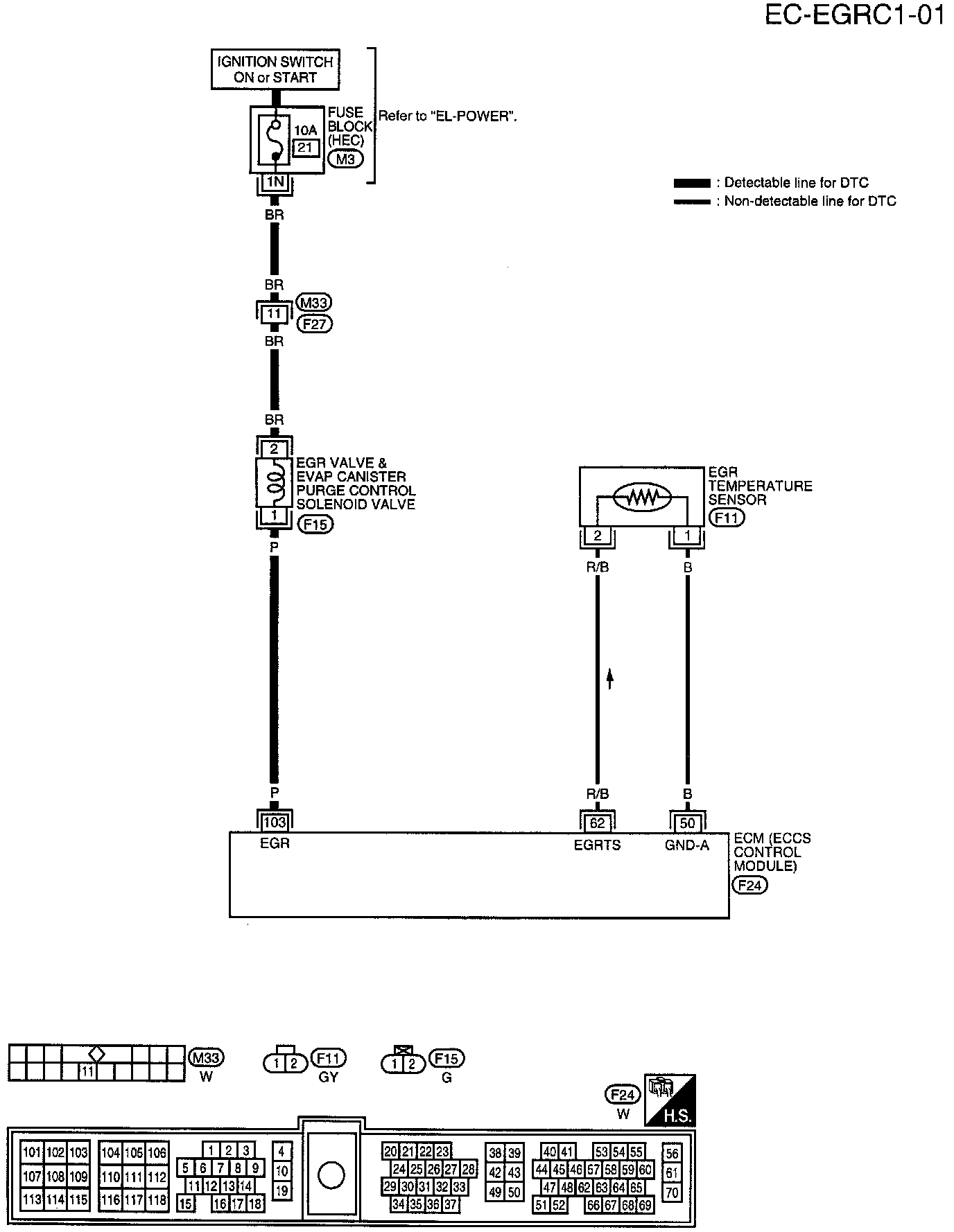
WIRING DIAGRAM
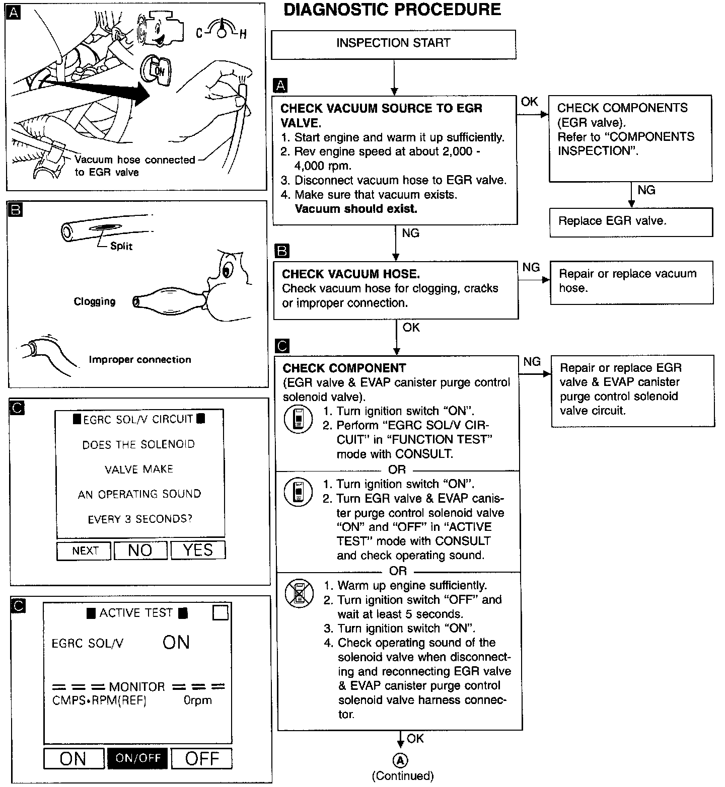
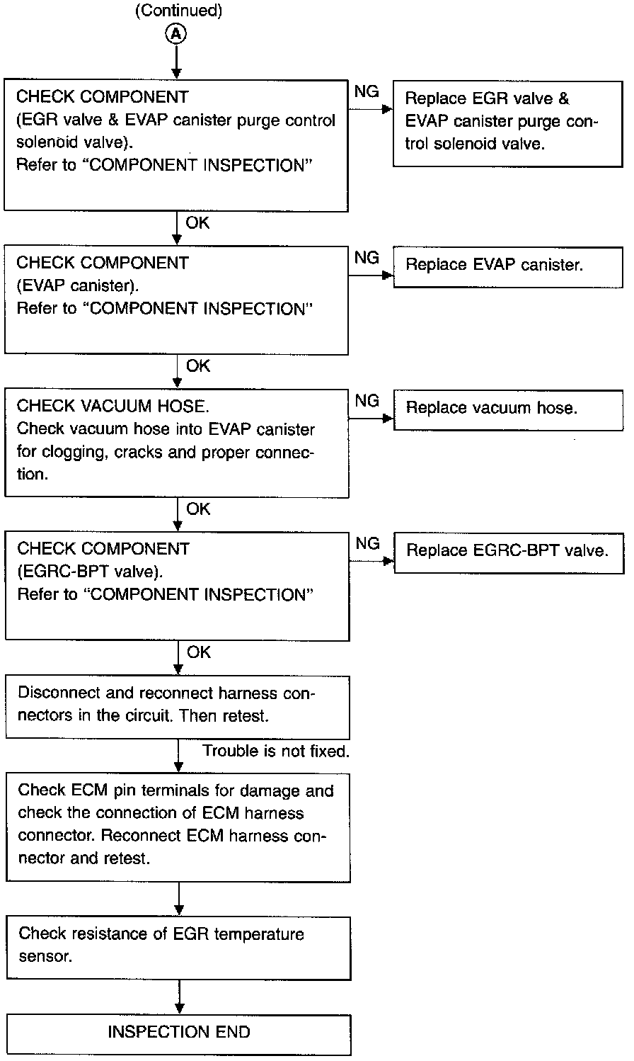
DIAGNOSTIC PROCEDURE
COMPONENT INSPECTION
EGR Valve
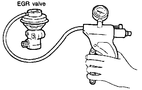
Apply vacuum to EGR vacuum port with a hand vacuum pump.
EGR valve spring should lift.
If NG, replace EGR valve.
EGR Valve & EVAP Canister Purge Control Solenoid Valve
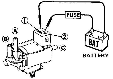
Check solenoid valve, following the table as shown below:
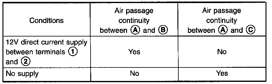
If NG, replace EGR valve & EVAP canister purge control solenoid valve.
EVAP Canister
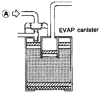
Gently blow air from (A).
No leakage should exist.
EGR Temperature Sensor
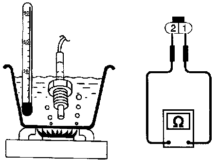
Check resistance change and resistance value.
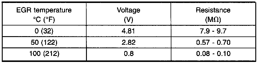
If NG, replace EGR temperature sensor.
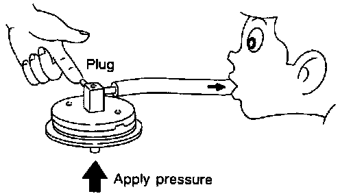
EGRC-BPT Valve
1. Plug one of two ports of EGRC-BPT valve.
2. Vacuum from the other port and check for leakage while applying a pressure above 0.981 kPa (100 mmH2O, 3.94 inH20) from under EGRC-BPT valve.
3. If a leakage is noted, replace the valve.