DTC 1101
DESCRIPTION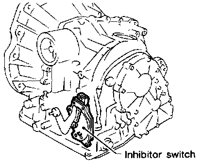
INHIBITOR SWITCH
Detects the selector lever position and sends a signal to the A/T control unit.
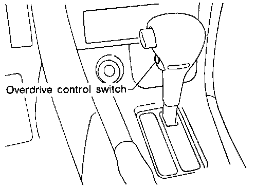
OVERDRIVE CONTROL SWITCH
Detects the overdrive control switch position (ON or OFF) and sends a signal to the A/T control unit.
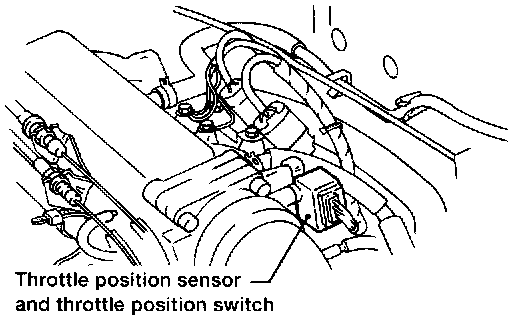
THROTTLE POSITION SWITCH
Consists of a wide-open throttle position switch and a closed throttle position switch.
The wide-open position switch sends a signal to the A/T control unit when the throttle valve is open at least 1/2 of the full throttle position. The closed throttle position switch sends a signal to the A/T control unit when the throttle valve is fully closed.
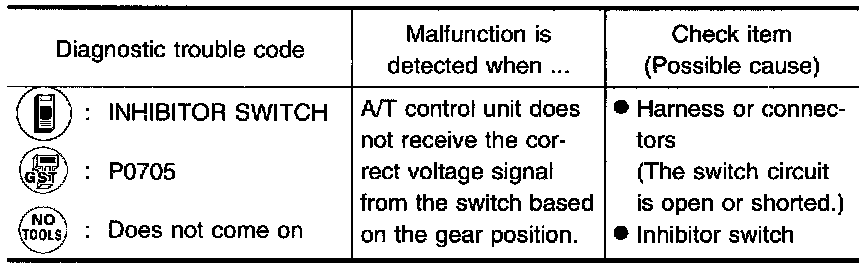
Diagnostic Trouble Code (DTC) Confirmation Procedure
After the repair, perform the following procedure to confirm that the malfunction is eliminated
With Consult
1. Start engine.
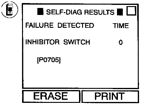
2. Select "SELF-DIAG RESULTS" mode for ECM with CONSULT.
3. Drive vehicle under the following conditions: Selector lever in "D", overdrive control switch in OFF position, vehicle speed higher than 10km/h (6 MPH), throttle opening greater than 1/2 of the full throttle position and driving for more than 5 seconds.
OR
With GTS
1. Start engine.
2. Drive vehicle under the following conditions: Selector lever in "D", overdrive control switch in OFF position, vehicle speed higher than 10 km/h (6 MPH), throttle opening greater than 1/2 of the full throttle position and driving for more than 5 seconds.
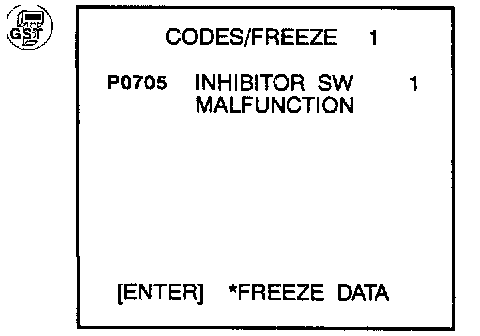
3. Select "MODE 7" with GST.
OR
No Tools
1. Start engine.
2. Drive vehicle under the following conditions: Selector lever in "D", overdrive control switch in OFF position, vehicle speed higher than 10km/h (6 MPH), throttle opening greater than 1/2 of the full throttle position and driving for more than 5 seconds.
3. Perform self-diagnosis for ECM.
Refer to "Malfunction Indicator Lamp (MIL)", "ON BOARD DIAGNOSTIC SYSTEM DESCRIPTION".
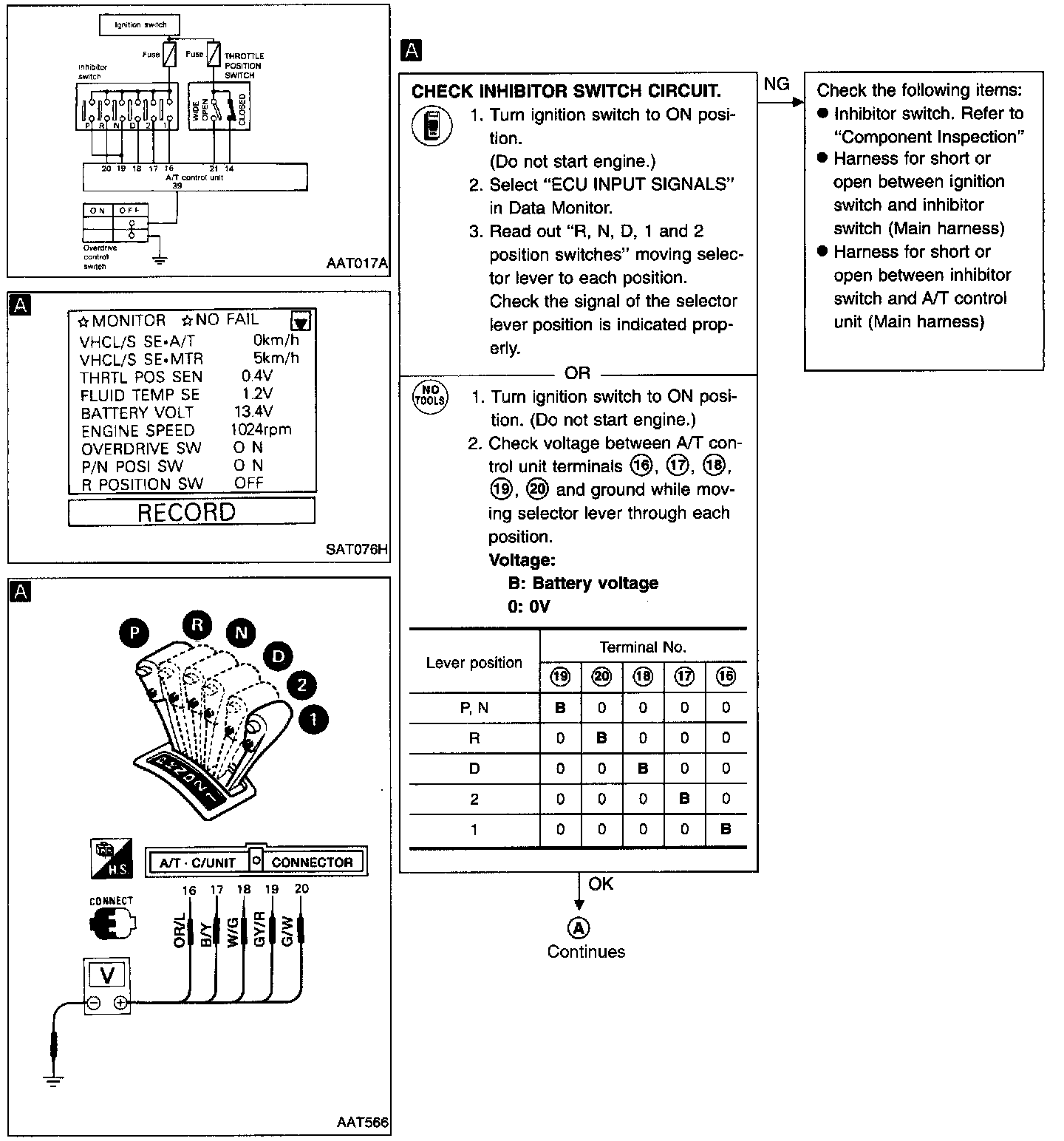
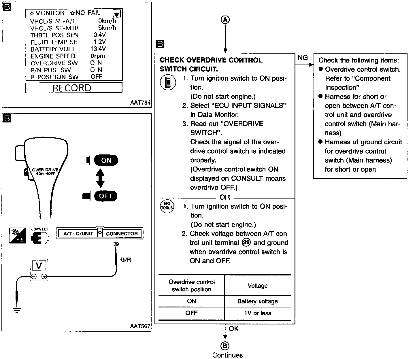
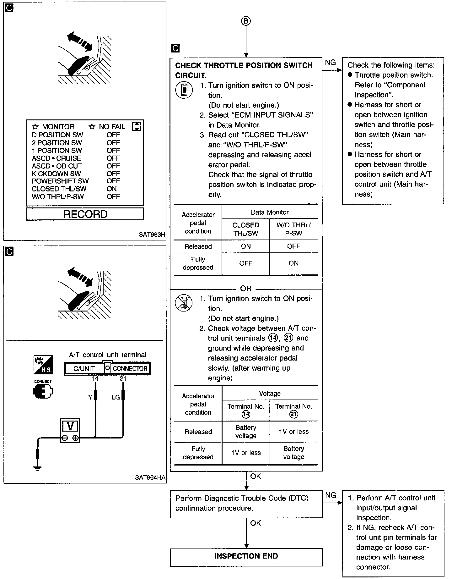
DIAGNOSTIC PROCEDURE
COMPONENT INSPECTION
Inhibitor Switch
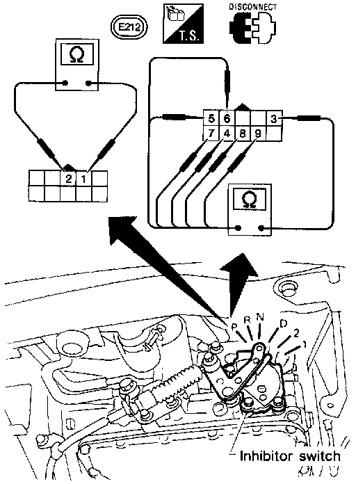
1. Check continuity between terminals (1) and (2) and between terminals (3) and (4), (5), (6), (7), (8), (9) while moving selector lever through each position.
Lever position / Terminal No.
P / (3)-(4), (1)-(2)
R / (3)-(5)
N / (3)-(6), (1)-(2)
D / (3)-(7)
2 / (3)-(8)
1 / (3)-(9)
Overdrive Control Switch
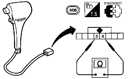
- Check continuity between two terminals.
Overdrive control switch position / Continuity
ON / No
OFF / Yes
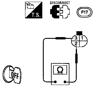
THROTTLE POSITION SWITCH
Closed throttle Position Switch (idle position)
- Check continuity between terminals (2) and (3).
Accelerator pedal condition / Continuity
Released / Yes
Depressed /No
- To adjust closed throttle position switch, Refer to "Basic Inspection".
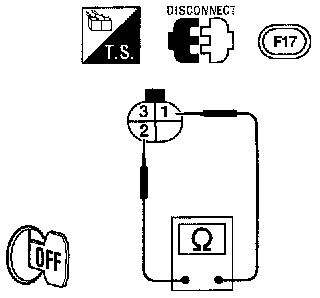
Wide Open Throttle Position Switch
- Check continuity between terminals (1) and (2).
Accelerator pedal condition / Continuity
Released / No
Depressed(fully) / Yes