Transfer Parts to New Long Engine Assembly
1. Remove the intake manifold: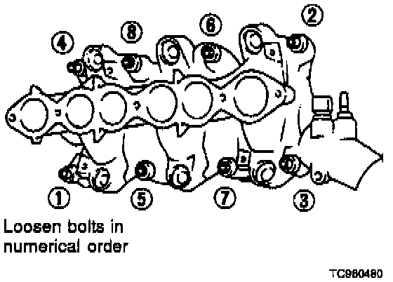
A. The following parts should be disconnected to remove the intake manifold:
^ All fuel injector harnesses
^ Fuel tube assembly (secured by four bolts)
^ Engine coolant temperature sensor harness connector.
^ Thermal transmitter harness connector.
^ Water hose from thermostat housing.
B. Remove intake manifold collector, loosen intake manifold bolts in numerical order and remove the intake manifold.
NOTE:
The thermostat housing does not have to be removed from the suction pipe.
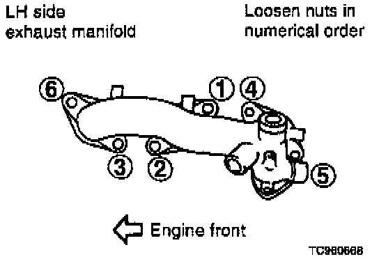
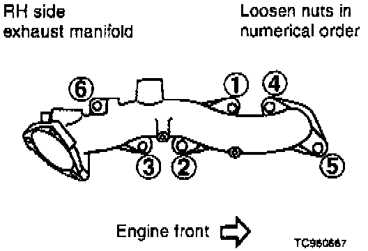
2. Remove exhaust manifold nuts in numerical order, then remove exhaust manifolds.
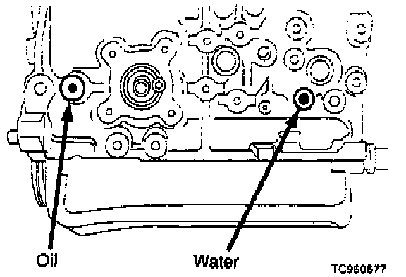
3. Remove one water jacket plug located near cylinder # 1, and one oil gallery plug located near cylinder # 5. Apply sealant to the water and oil plug threads, and install on the new block. Be careful not to allow any foreign material into the oil passage.
NOTE:
Remove the original gasket sealer from the bolt threads.
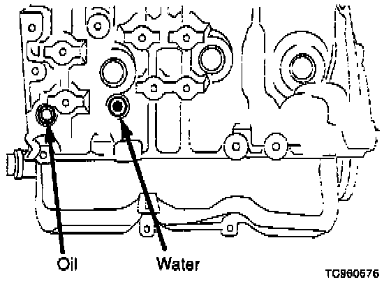
4. Remove the water jacket plug located near cylinder # 2, on the outside of the block. Apply sealant to water plug threads, and install the plug on the new block. Remove the oil plug to the left of cylinder # 2. Replace the washer (P/N 11026-01M02) on the oil gallery plug, and install the plug on the new block. Be careful not to allow any foreign material into the oil passage.
NOTE:
Remove the original gasket sealer from the bolt threads.
5. Install new oil filter mounting stud.
6. Carefully remove the dipstick guide tube. Apply Loctite(R) 540 or equivalent to the dipstick tube, and press it into the new block. Install in the same position on the new block. Check the new block for alternate dipstick tube installation points, which may not be plugged. Install brass plugs if necessary (P/N 11022-U6700).
7. Install connector to knock sensor on top of block before thermostat housing and intake manifold. There is limited access to the knock sensor after these parts are installed.
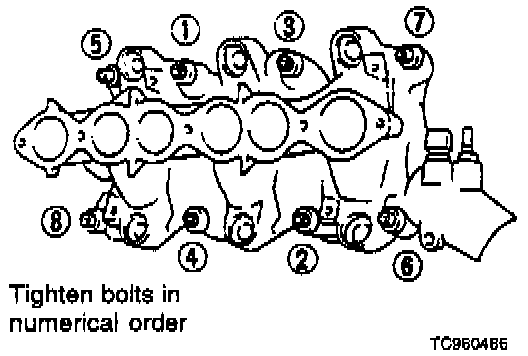
8. Install intake manifold. Install all parts removed in step 1, under Transfer Parts to New Long Engine Assembly. Tighten all bolts in numerical order.
Tightening procedure:
A. Tighten all bolts and nuts to 2.2-3.6 ft-lb (3-5 N.m, 0.3-0.5 kg-m).
B. Tighten all bolts to 12-14 ft-lb (16-20 N.m, 1.6-2.0 kg-m).
Tighten all nuts to 17-20 ft-lb (24-27 N.m, 2.4-2.8 kg-m).
C. Tighten all bolts to 12-14 ft-lb (16-20 N.m, 1.6-2.0 kg-m).
Tighten all nuts to 17-20 ft-lb (24-27 N.m, 2.4-2.8 kg-m).
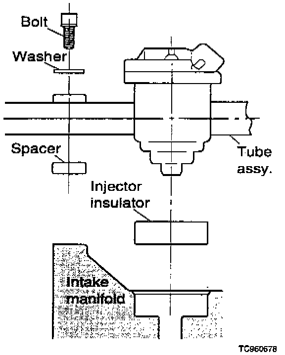
9. Install the fuel tube assembly:
^ Tape the fuel tube spacers to the fuel tube before installation.
^ Install new fuel injector insulators. Ensure the insulators are properly seated in the intake manifold.
^ Torque the 4 fuel tube securing bolts to 12-15 ft-lb (16-21 N.m, 1.6-2.1 kg-m).
10. On M/T vehicles, install a new pilot bushing (P/N 32202-B9500). On M/T vehicles, install converter pilot P/N 12330-14L00.