Valve Clearance: Adjustments
Fig. 18 Valve Adjusting Tools.:
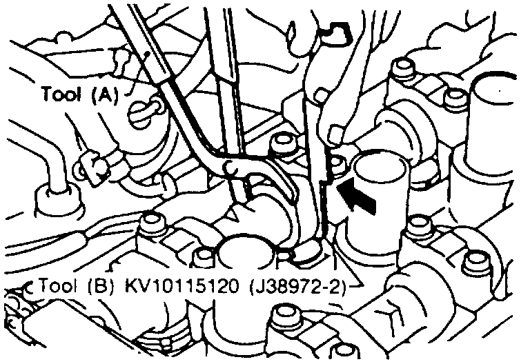
Fig. 19 Cam Tool (A) Installation.:
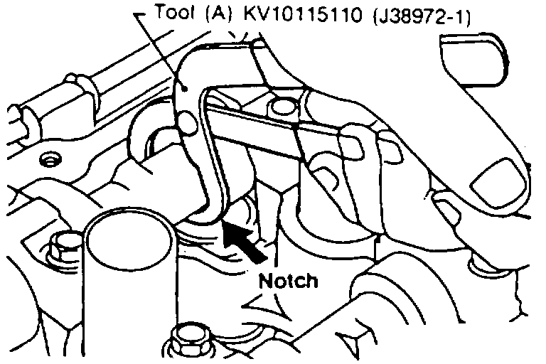
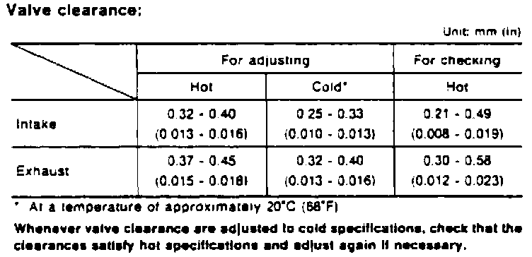
Fig. 20 Valve Clearance Specifications.:
1. Remove rocker cover and all spark plugs.
2. Set No. 1 cylinder at TDC on its compression stroke.
3. Align pointer with TDC mark on crankshaft pulley.
4. Valve lifters on No. 1 cylinder should be loose and valve lifters on No. 4 cylinder should be tight. If lifters are as specified, proceed to step 5. If lifters are not as specified, turn crankshaft 360° and realign pointer with TDC mark on crankshaft pulley, then proceed to step 5.
5. With engine at operating temperature, use a feeler gauge to measure clearance between valve lifter and camshaft as follows:
a. Check clearance on No. 1 and No. 2 intake valves. Clearance should be.008-0.019 inch.
b. Check clearance on No. 1 and No. 3 exhaust valves. Clearance should be 0.012-0.023 inch.
c. Turn crankshaft 360° and align pointer with TDC mark on crankshaft pulley.
d. Check clearance on No. 3 and No. 4 intake valves. Clearance should be 0.008-0.019 inch.
e. Check clearance on No. 2 and No. 4 exhaust valves. Clearance should be 0.012-0.023 inch.
6. Adjust valves while engine is cold using cam turning tool (A) No. KV10115110 and valve lifter holding tool (B) No. KV10115120, or equivalents, Fig. 18.
7. Turn crankshaft to position cam lobe on camshaft of valve to be adjusted upward.
8. Install tool (A) around camshaft, Fig. 19.
9. Rotate tool (A) so that lifter is pushed down.
10. Place tool (B) between camshaft and edge of valve filter to retain lifter.
11. Remove tool (A).
12. Remove adjusting shim using a screwdriver and a magnet.
13. Determine replacement adjusting shim size for intake valves using the following formula:
a. Use a micrometer to determine thickness of removed shim.
b. Calculate thickness of new shim so valve clearance becomes 0.010-0.013 inch by subtracting 0.0146 inch from measured valve clearance (M). Then add value of thickness of removed shim (R) to give thickness of new shim (N). N = R + (M - 0.0146 inch).
14. Determine replacement adjusting shim size for exhaust valves using the following formula:
a. Use a micrometer to determine thickness of removed shim.
b. Calculate thickness of new shim so valve clearance becomes 0.013-0.016 inch by subtracting 0.0157 inch from measured valve clearance (M). Then add value of thickness of removed shim (R) to give thickness of new shim (N). N = R + (M -0.0157 inch).
15. Select new shim with thickness as close as possible to calculated value.
16. Install selected shim and check valve clearance, Fig. 20.