Assembly
ASSEMBLY1. Install upper, inter and lower body.
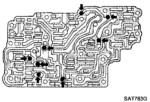
a. Place oil circuit of upper body face up. Install steel balls in their proper positions.
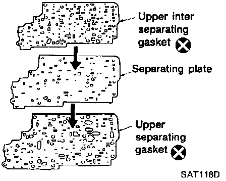
b. Install upper separating gasket, upper inter separating gasket and upper separating plate in order shown in illustration.

c. Install reamer bolts Of from bottom of upper body and install separating gaskets and separating plate as a set on upper body using reamer bolts as guides.
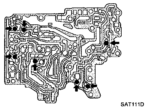
d. Place lower body side of inter body face up. Install steel balls in their proper positions.
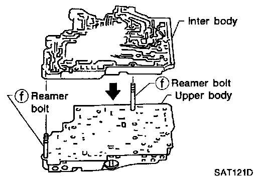
e. Install inter body on upper body using reamer bolts (f) as guides
- Be careful not to dislocate or drop steel balls.
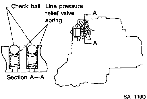
f. Install steel balls and relief valve springs in their proper positions in lower body.
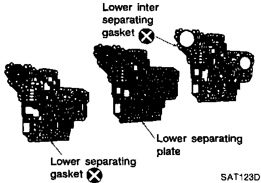
g. Install lower separating gasket, inter separating gasket and lower separating plate in order shown in illustration.
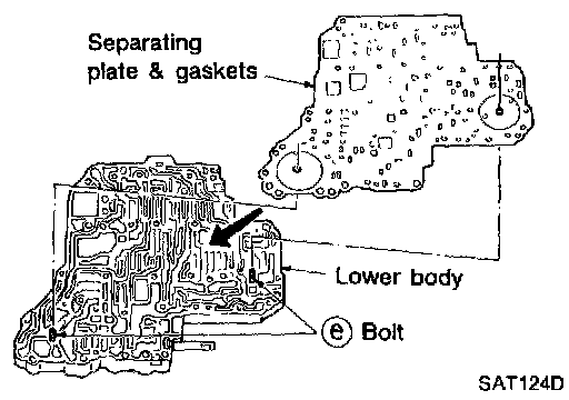
h. Install support plate fixing bolts (e) from bottom of lower body and install separating gaskets and separating plate as a set on lower body using bolts (e) as guides.
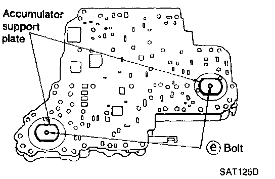
i. Temporarily install support plates on lower body.
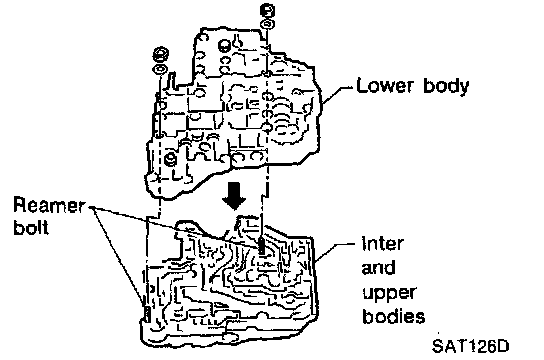
j. Install lower body on inter body using reamer bolts (f) as guides and tighten reamer bolts (f) slightly.
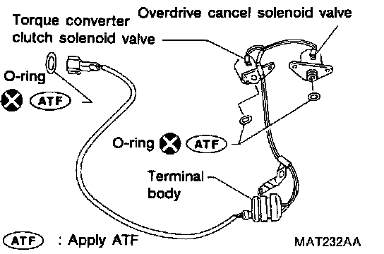
2. Install O-rings to OD cancel solenoid valve, torque converter clutch solenoid valve and harness connector.
- Apply ATF to O-rings.
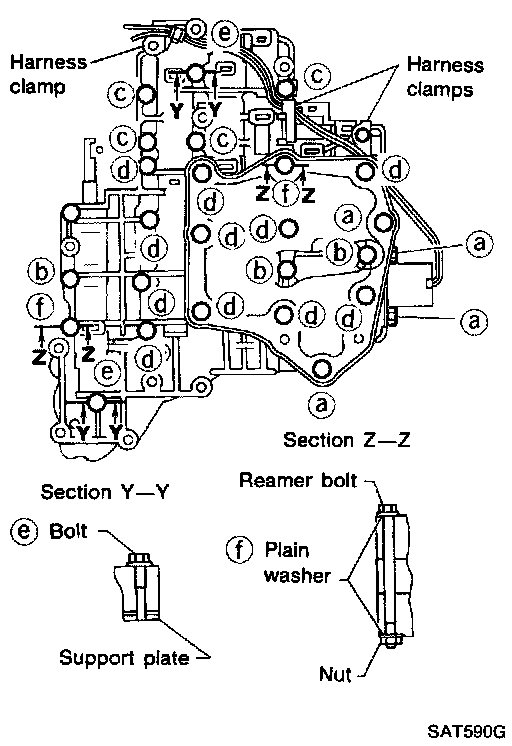
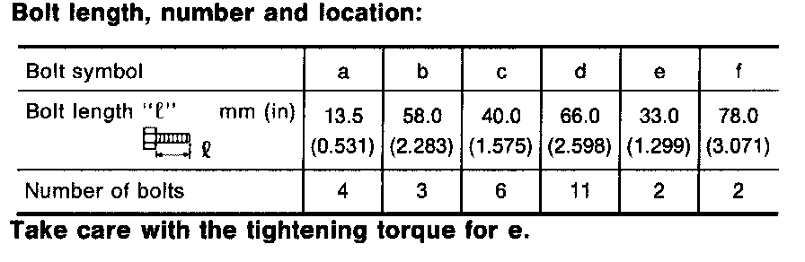
3. Install and tighten bolts.
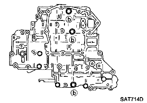
a. Install and tighten bolts (b) slightly.
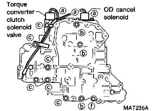
b. Install OD cancel solenoid valve and torque converter clutch solenoid valve to lower body.
c. Install and tighten bolts (a) and (c) slightly.
d. Remove both reamer bolts (f) previously installed as guides. Install one reamer bolt (f) (marked in illustration) from lower body side.
e. Tighten bolts (a), (b), (c) and (f) to specified torque.
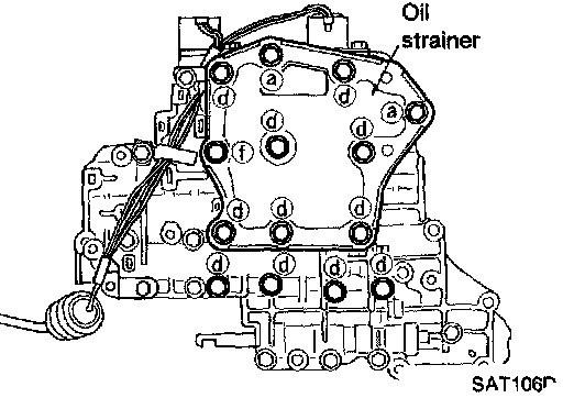
f. Install oil strainer and the other reamer bolt (f) (marked in illustration), then tighten bolts (a), (d) and (f) to specified torque.
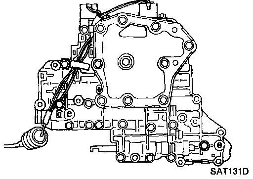
g. Install support plates and tighten bolts (e) to specified torque.
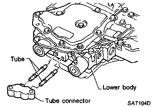
h. Install tube connector and tubes to lower body.
- Install oil circuit side of tube connector face up.