Disassembly
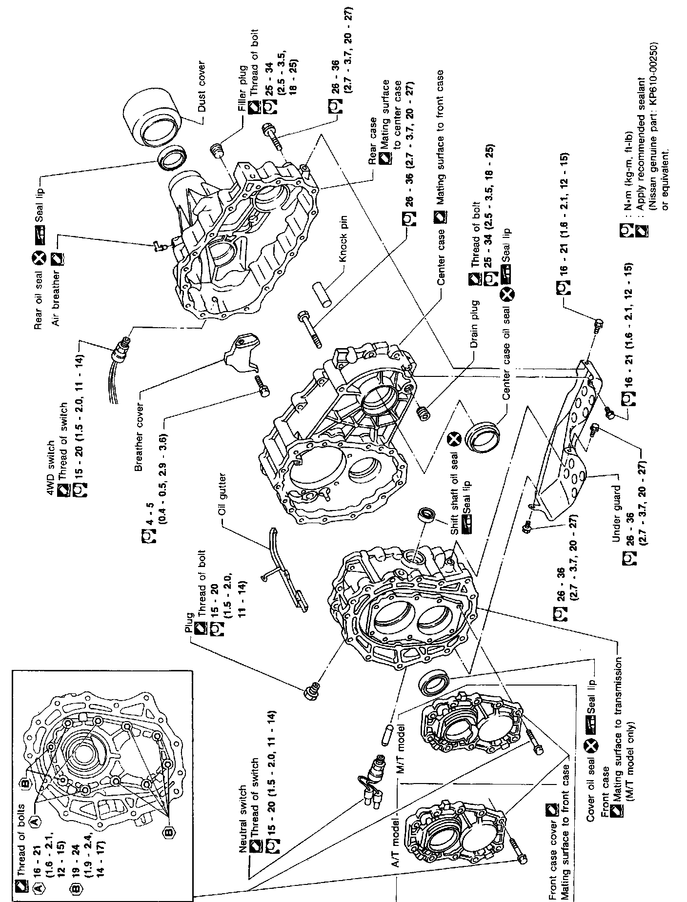
Case Components
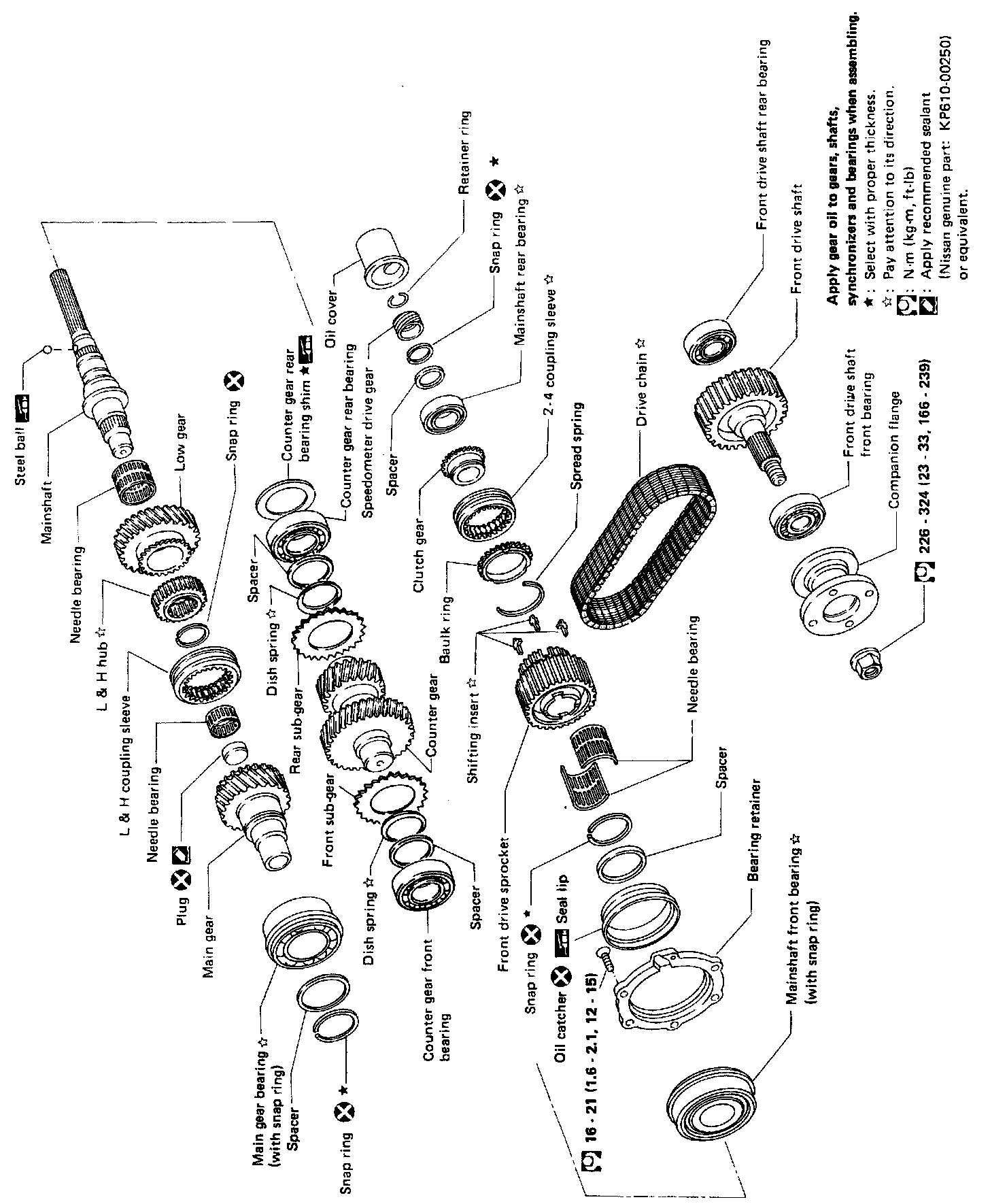
Gear Components
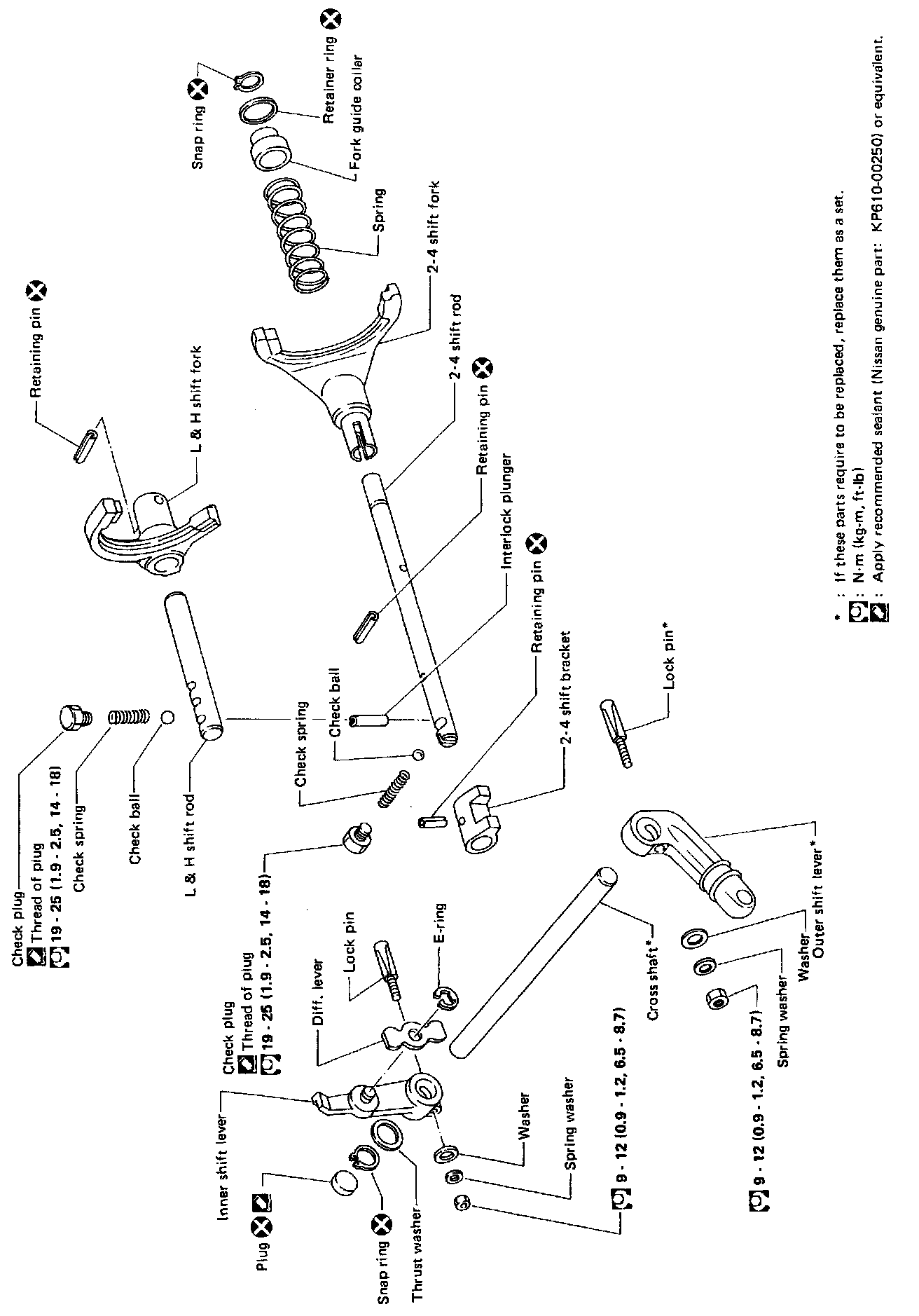
Shift Control Components
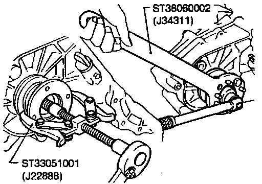
1. Remove nut of companion flange.
2. Remove companion flange.
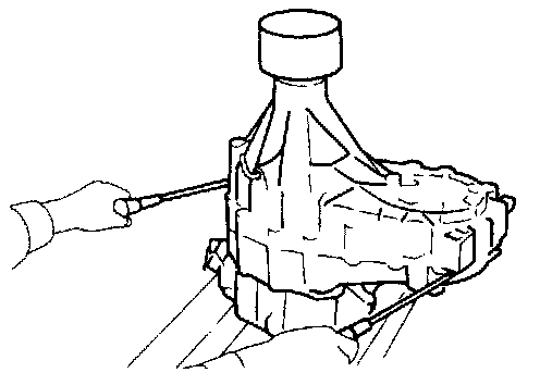
3. Remove 4WD switch.
4. Remove rear case.
Be careful not to damage the mating surface.
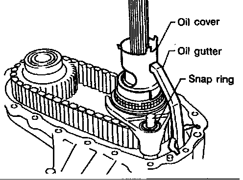
5. Remove oil cover and oil gutter.
6. Remove snap ring from 2-4 shift rod.
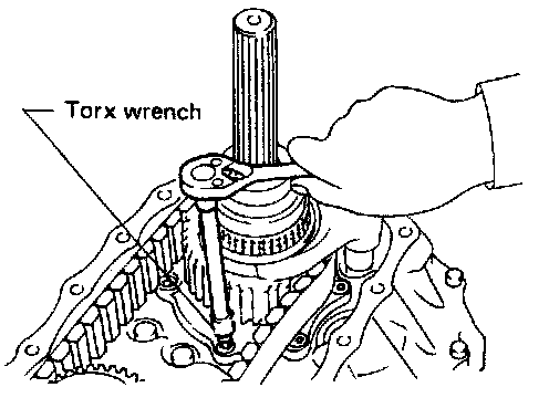
7. Remove bolts securing bearing retainer.
This step is necessary to remove mainshaft from center case.
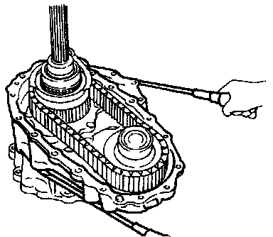
8. Remove bolts securing center case to front case and then separate center case and front case.
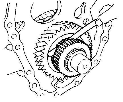
9. Measure end play of low gear.
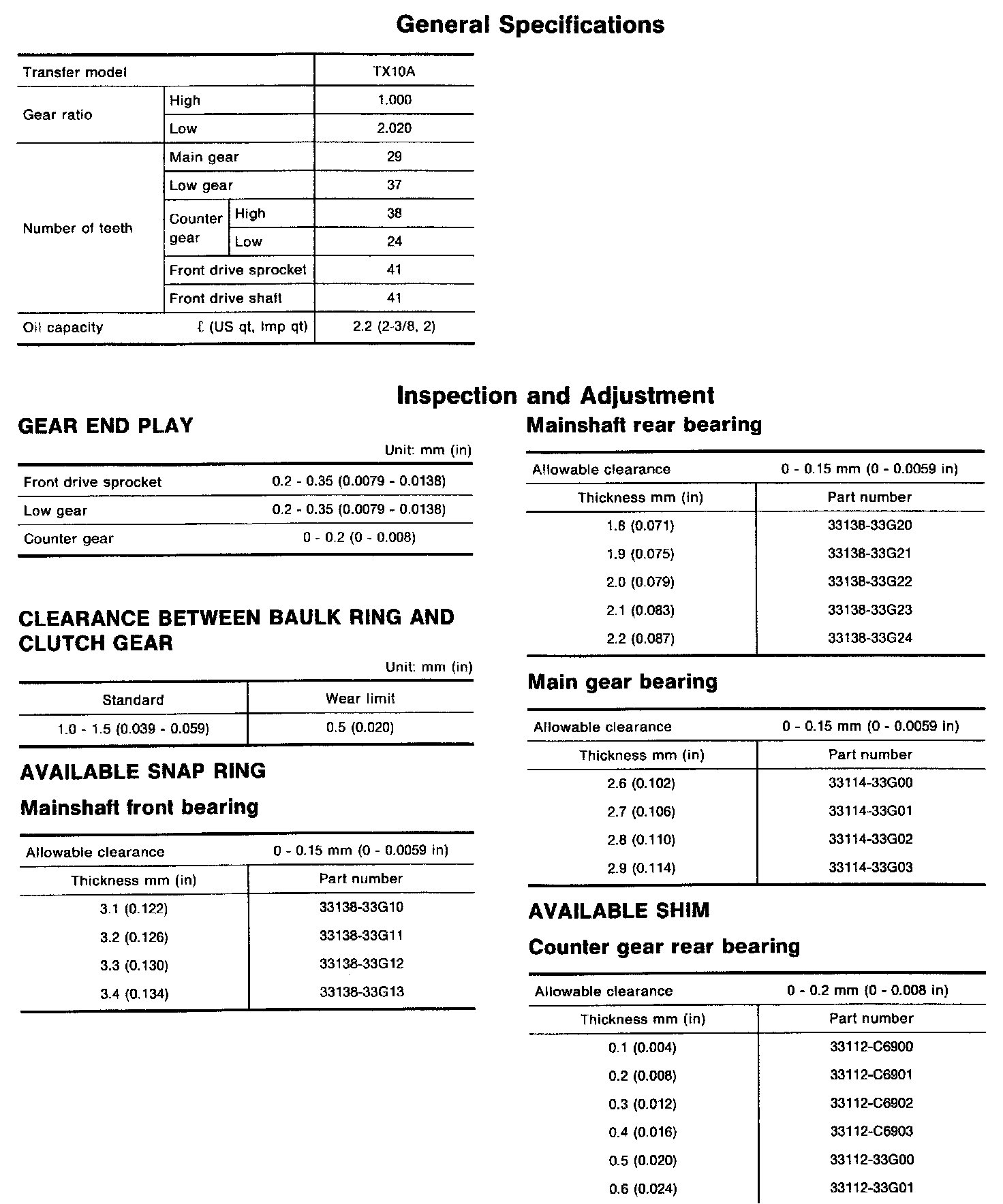
Standard: 0.2-0.35 mm (0.0079 - 0.0138 in)
If end play is beyond the maximum value, check low gear and L & H hub for wear.
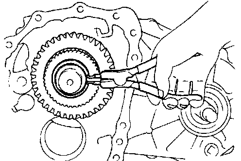
10. Disassemble center case assembly.
a. Remove snap ring from mainshaft.
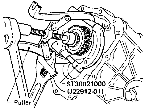
b. Pull out low gear with L & H hub.
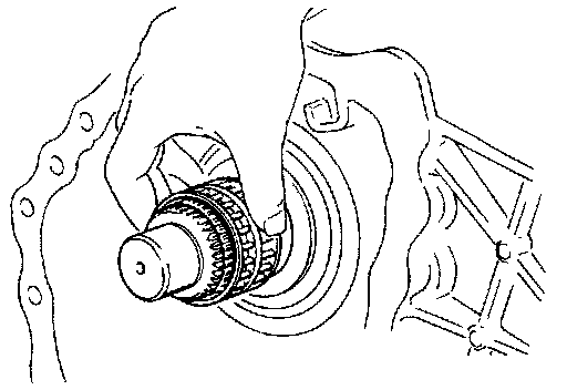
c. Remove needle bearing of low gear.
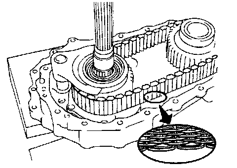
d. Make sure of the direction of the drive chain before removing it. (It must be reinstalled in the same direction). Check whether spring part of drive chain is installed on front or rear side.
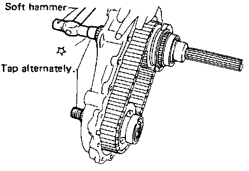
e. Remove mainshaft, front drive and drive chain as a set by tapping front end of mainshaft and front drive shaft alternately. Be careful not to bend drive chain.
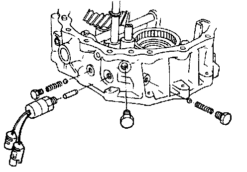
11. Disassemble front case assembly
a. Remove switch, plugs, check springs and check balls.
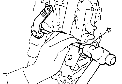
b. Remove outer shift lever.
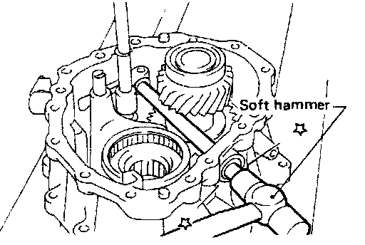
12. Remove lock pin of inner shift lever and drive out cross shaft with plug.
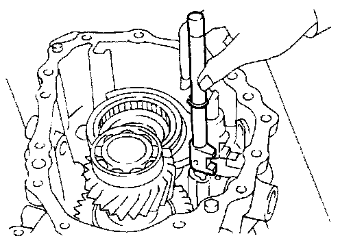
d. Remove 2-4 shift rod.
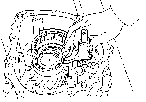
e. Remove L & H shift rod and fork assembly with coupling sleeve.
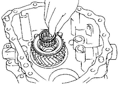
f. Remove needle bearing from main gear.
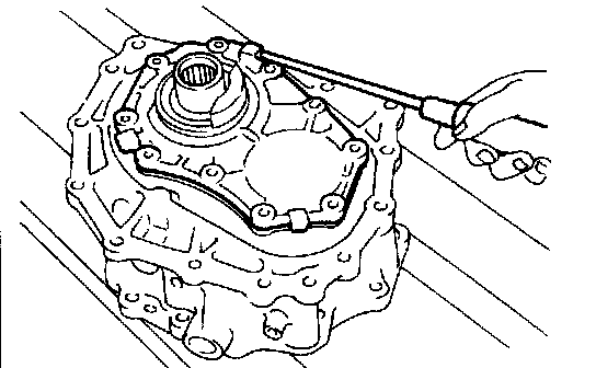
g. Remove bolts securing front case cover and then remove case.
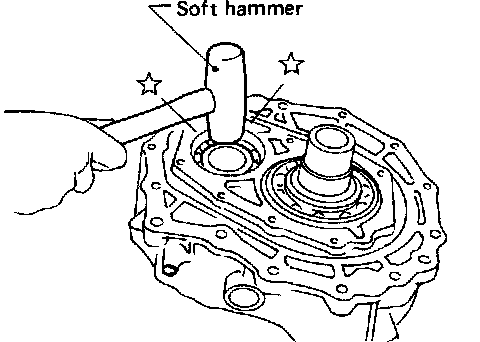
h. Remove counter gear by tapping
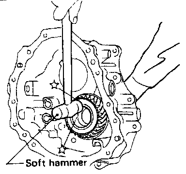
i. Remove main gear by tapping lightly.
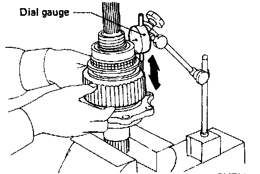
Mainshaft DISASSEMBLY
1. Check end play of front drive sprocket.
Standard: 0.2-0.35 mm (0.0019 - 0.0138 in)
If end play is beyond the maximum value, check front drive sprocket and clutch gear for wear.
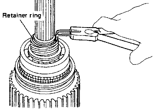
2. Remove retainer ring, speedometer drive gear and steel ball.
Be careful not to lose the steel ball.
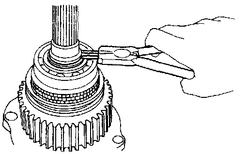
3. Remove snap ring and spacer.
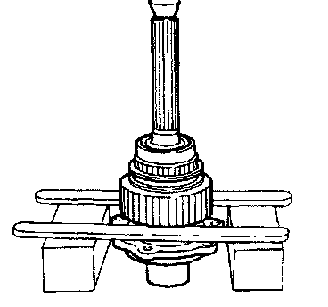
4. Press out front drive sprocket with mainshaft rear bearing and clutch gear together.
5. Remove needle bearing.
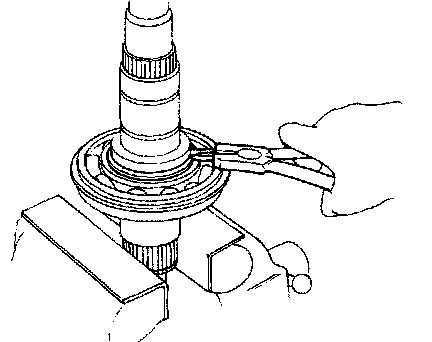
6. Remove bearing retainer and then remove snap ring and spacer.
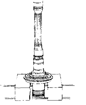
7. Press out mainshaft front bearing from mainshaft.
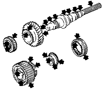
INSPECTION GEAR AND SHAFT
- Check gears for excessive wear, chips or cracks.
- Check shaft for cracks, wear or bending.
- Check coupling sleeve for wear or damage.
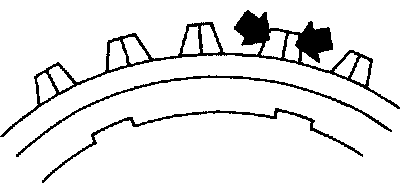
Baulk ring
- Check baulk ring for cracks or deformation.
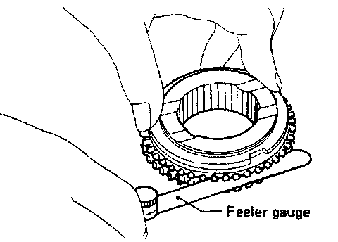
- Measure clearance between baulk ring and gear.

Baulk ring to gear clearance:
Bearing
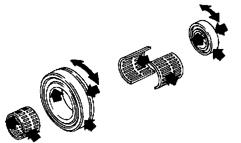
- Make sure bearings roll freely and are free from noise, crack, pitting or wear
ASSEMBLY
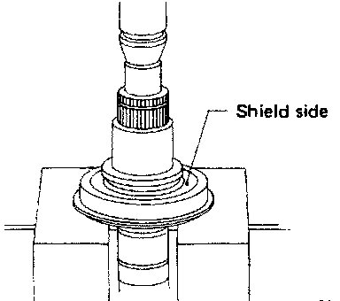
1. Press mainshaft front bearing onto mainshaft.
Pay special attention to its direction.
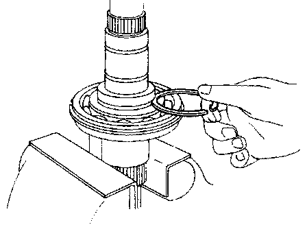
2. Install spacer.
3. Select snap ring with proper thickness and install it.
Allowable clearance between snap ring and groove: 0-0.15 mm (0 - 0.0059 in)
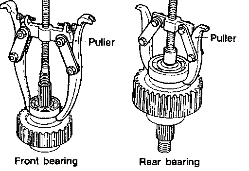
FRONT DRIVE SHAFT DISASSEMBLY
- Front drive shaft front bearing and rear bearing
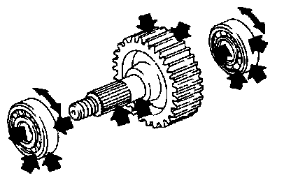
INSPECTION SPROCKET SHAFT
- Check sprocket for excessive wear, chips or cracks.
- Check shaft for cracks or wear.
Bearing
- Make sure bearings roll freely and are free from noise, crack, pitting or wear.
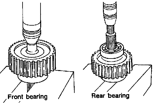
ASSEMBLY
- Press front drive shaft front bearing and rear bearing.
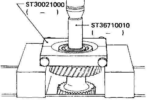
COUNTER GEAR DISASSEMBLY
1. Press out counter gear front bearing and then remove front sub-gear, spacer and dish spring.
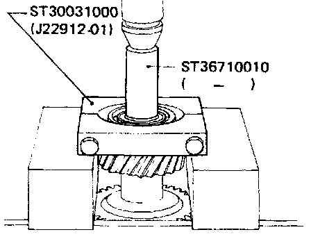
2. Press out counter gear rear bearing and then remove rear sub-gear, spacer and dish spring.
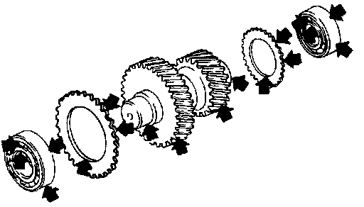
INSPECTION GEAR AND SHAFT
- Check gears for excessive wear, chips or cracks
- Check shaft for cracks or wear.
Bearing
- Make sure bearings roll freely and are free from noise, crack, pitting or wear.
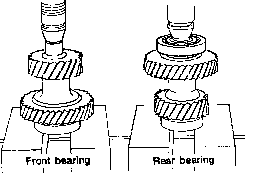
ASSEMBLY
1. Install front sub-gear, dish spring and spacer, and then press on counter gear front bearing.
2. Install rear sub-gear, dish spring and spacer, and then press on counter gear rear bearing.
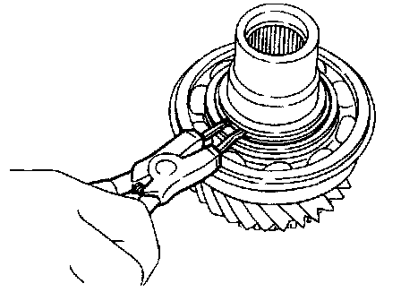
MAIN GEAR DISASSEMBLY
Main gear bearing
1. Remove snap ring and spacer.
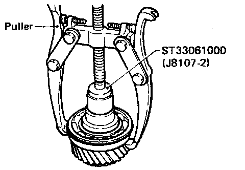
2. Pull out main gear bearing.
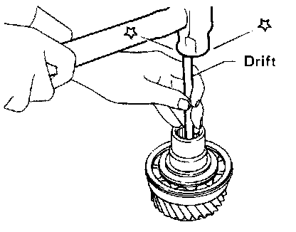
Plug
Always replace it with new one whenever it is removed.
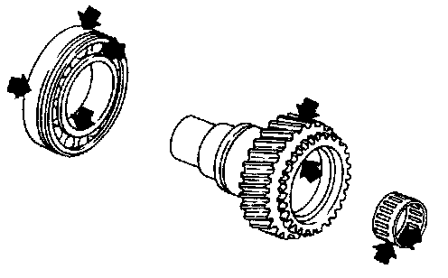
INSPECTION GEAR AND SHAFT
- Check gears for excessive wear, chips or cracks.
- Check shaft for cracks or wear.
Bearing
- Make sure bearings roll freely and are free from noise, crack, pitting or wear.
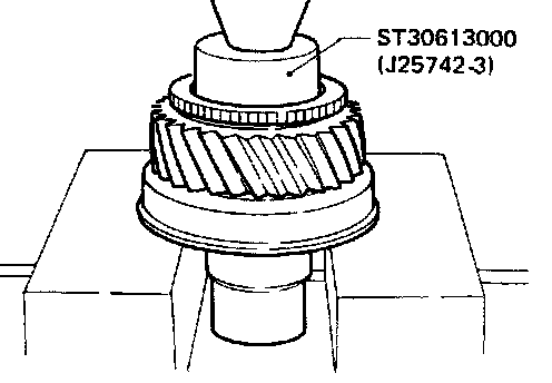
ASSEMBLY MAIN GEAR BEARING
1. Press on main gear bearing.
2. Install spacer.
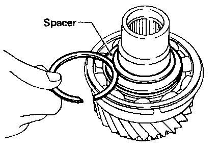
3. Select snap ring with proper thickness and install it.
Allowable clearance between snap ring and groove: 0-0.15 mm (0 - 0.D059 in)
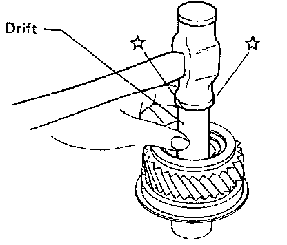
PLUG
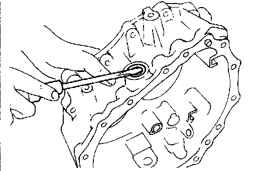
FRONT CASE SHIFT SHAFT OIL SEAL REMOVAL
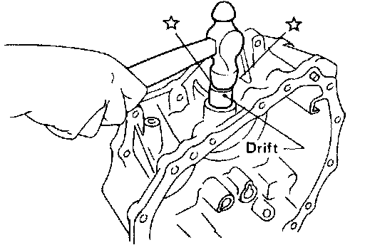
INSTALLATION
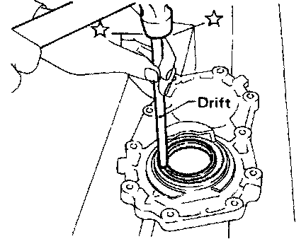
FRONT CASE COVER OIL SEAL REMOVAL
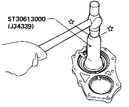
INSTALLATION
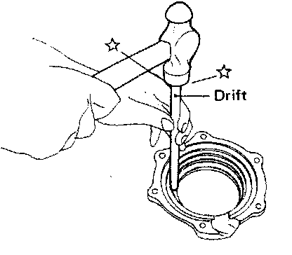
BEARING RETAINER OIL CATCHER REMOVAL
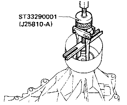
INSTALLATION
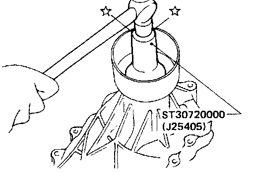
REAR CASE OIL SEAL REMOVAL
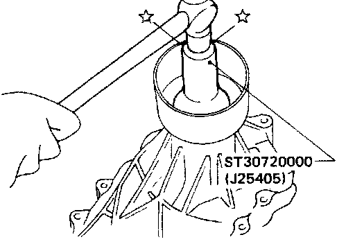
INSTALLATION
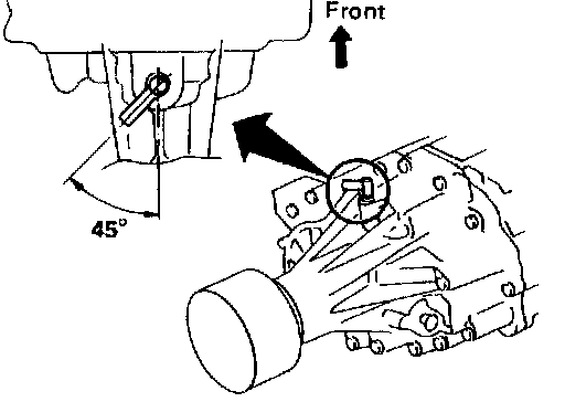
AIR BREATHER
Install as shown in illustration.
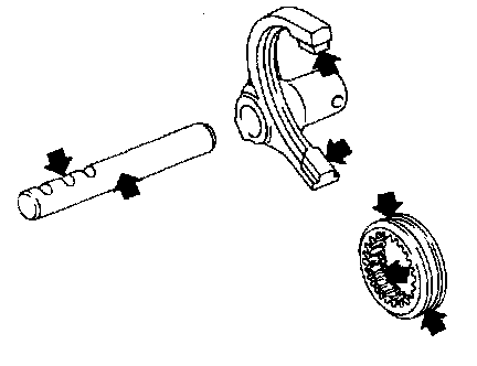
SHIFT CONTROL COMPONENTS INSPECTION
- Check contact surface and sliding surface for wear, scratches, projections or other faulty conditions.
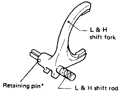
L & H SHIFT ROD & FORK
assemble as shown in illustration.
* Retaining pin is the same size as the one for 2-4 shift rod.
2-4 SHIFT ROD & FORK
Assemble as shown in illustration.
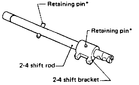
* Retaining pins are the same size.
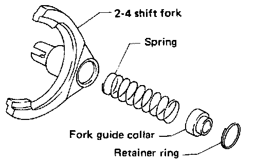
Pay special attention to the direction of fork guide collar.