Torsion Bar: Service and Repair
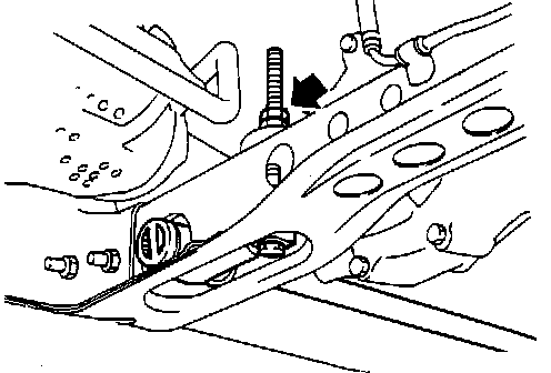
Fig. 2:
REMOVAL
1. Loosen the tension on the tension bars.
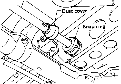
2. Remove the dust boot and remove the snap ring.
FIGURE 4:
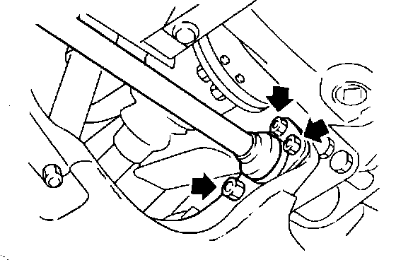
3. Remove the front torsion bar mounts (two 14 mm and one 19 mm nut per side) (Figure 4) and remove the torsion bars.
INSTALLATION
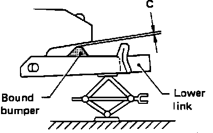
1. Raise the lower control arm until the clearance between the compression bumper and the frame is:
CLEARANCE C
0 mm (0 in.)
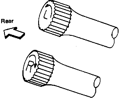
2. Install the torsion bar spring noting left and right springs.
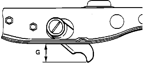
3. Adjust the anchor arm as shown above to the following dimension:
DIMENSION G
50 - 60 mm (1.97 - 2.36 in.)
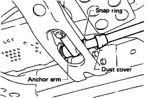
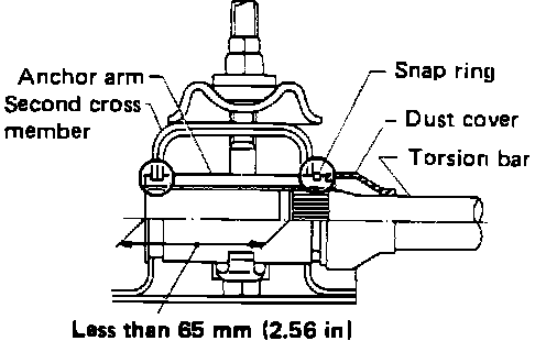
4. Install the snap ring and the dust cover making sure the snap ring is properly installed on the anchor arm groove.
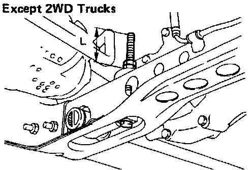
Except 2WD Trucks 17 mm (3.03 in)
5. Bounce vehicle with tires on ground (Unladen) to eliminate friction of suspension.
6. Measure vehicle posture "H".
(1) Exercise the front suspension by bouncing the front of the vehicle 4 or 5 times to ensure that the vehicle is in a neutral height attitude.
(2) Measure vehicle posture ... Dimension "H".
H = A - B mm (in) "Unladen"
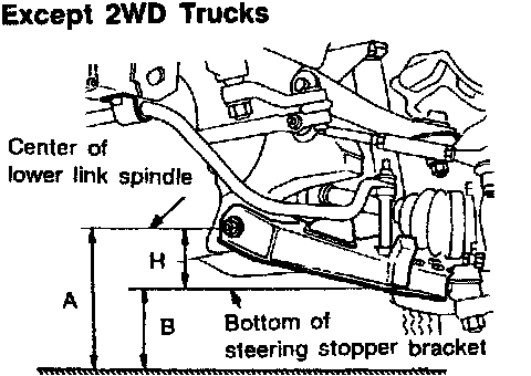
7. If height of the vehicle is not within allowable limit, adjust vehicle posture/ride height. AlignmentSee Ride Height.
8. Check wheel alignment if necessary.