Installation
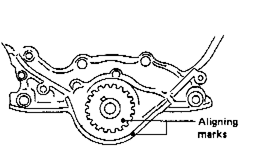
1. Align crank sprocket alignment mark with mark on oil pump body as shown.
2. Confirm that knock pin on camshaft is set at the top.
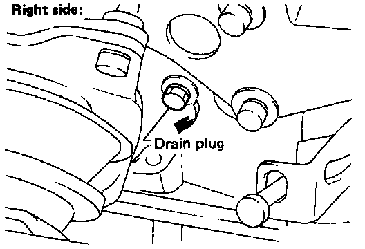
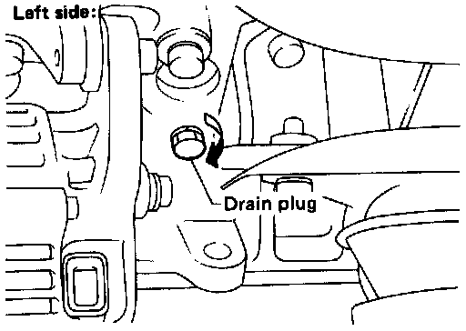
3. Apply sealant to drain plug threads and install both drain plugs.
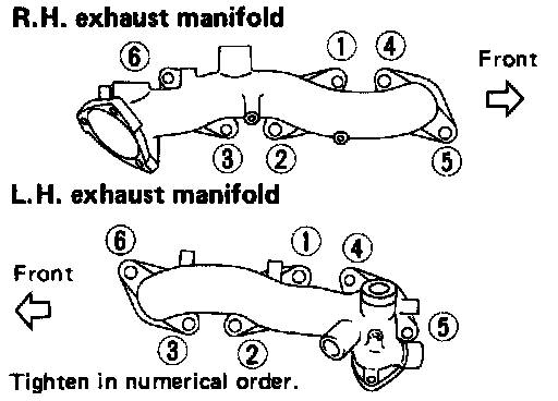
4. Install exhaust manifolds. In the order shown above, torque to 18 - 22 Nm (13 - 16 ft.lbs).
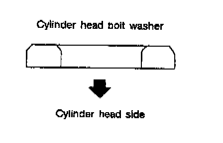
5. Using new gaskets, install cylinder heads. Install the washers as shown above between bolts and cylinder head.
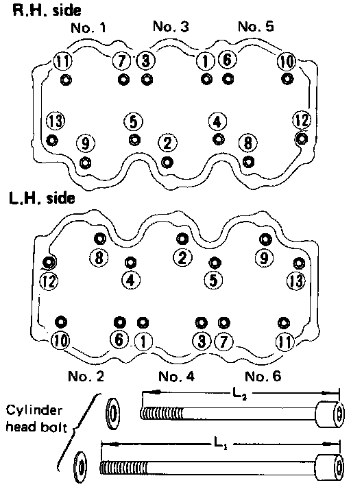
6. Torque head bolts in order shown above as follows:
^ Torque all bolts to 29 Nm (22 ft.lbs)
^ Torque all bolts to 59 Nm (43 ft.lbs)
^ Loosen all bolts completely
^ Torque all bolts to 29 Nm (22 ft.lbs)
^ Turn all bolts 60 - 65° clockwise. If an angle wrench is not available, torque all bolts to 54 to 64 Nm (40 - 47 ft.lbs).
Note: Bolts at positions 4, 5, 12 and 13 are longer than the others.
Rocker Arm Cover Assembly Sequence:
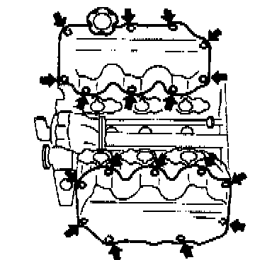
7. Install both valve covers.
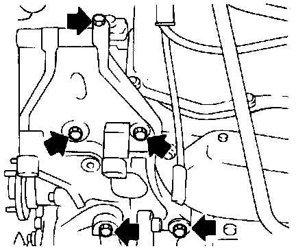
8. Install compressor and alternator brackets. Install compressor and alternator.
9. Install exhaust front tube to exhaust manifold.
Fig. 9 Camshaft Pulley Identification:
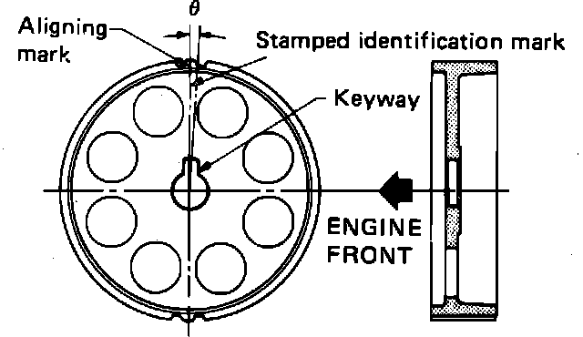
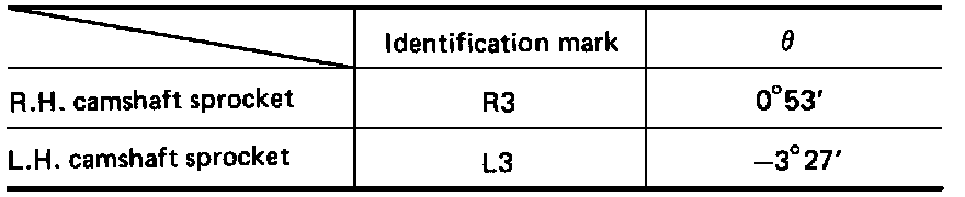
10. Install the rear belt cover and cam sprockets. The RH and LH cam sprockets are different parts, install them as shown.
11. Install timing belt and adjust tension as necessary.
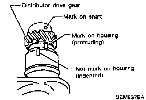
12. Align mark on shaft with protruding mark on housing as shown.
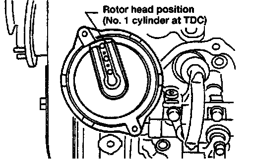
13. After installing, confirm that the distributor rotor head is set as shown above.
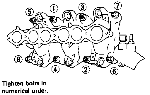
14. Using new gasket, install intake manifold. Torque bolts in sequence shown as follows:
^ Torque all bolts to 3 - 5 Nm (2.2 - 3.6 ft.lbs)
^ Torque all nuts to 3 - 5 Nm (2.2 - 3.6 ft.lbs)
^ Torque all bolts to 16 - 20 Nm (12 - 14 ft.lbs)
^ Torque all nuts to 24 - 27 Nm (17 - 20 ft.lbs)
^ Torque all bolts to 16 - 20 Nm (12 - 14 ft.lbs)
^ Torque all nuts to 24 - 27 Nm (127 - 20 ft.lbs)
15. Connect the water hose to the thermostat housing.
16. Connect the thermal transmitter harness connector and engine temperature switch harness connector.
17. Install the fuel rail assembly.
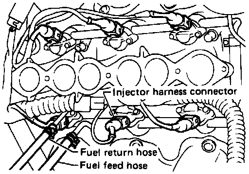
18. Connect all the injector connectors. Install the fuel feed and fuel return hoses to the fuel rail.
19. Install the intake manifold collector. Torque bolts to 4 - 5 Nm (2.9 - 3.6 ft.lbs).
20. Connect air duct hose, ground harness, EGR tube, and purge hose to canister.
21. Connect the vacuum hoses for the canister, master cylinder, and fuel pressure regulator.
22. Connect the PCV hose to the RH valve cover, heater hoses and water hoses to the collector.
23. Connect the following connectors:
^ EGR gas temperature sensor (California models only)
^ Air regulator
^ EGR control solenoid valve
^ Power transistor
^ Ignition coil
^ Throttle sensor and throttle valve switch
^ AAC valve
24. Install the ASCD and accelerator control cables.
25. Add coolant to system. Connect negative battery cable.
26. Start engine and check for leaks. Shut engine down and allow it to cool down.
27. Remove valve covers and check lifters.
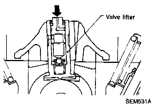
28. Push the hydraulic lifter plunger forcefully with your finger with the rocker in the free position.
29. If the lifter moves more than 1mm (0.04 in.), it may have air inside.
30. Bleed off air by running engine at 1,000 rpm under no load for about 10 minutes.
31. If lifters are still noisy, replace them and repeat from step 25.