Overhaul
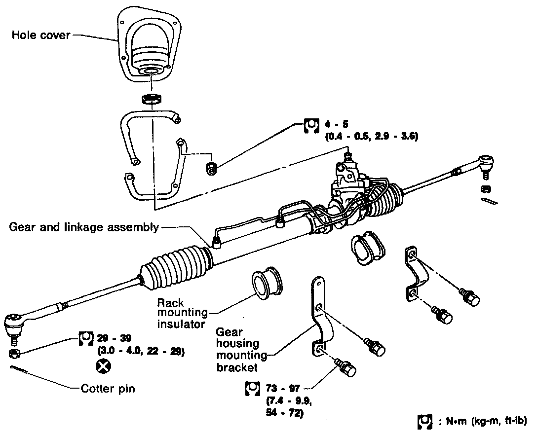
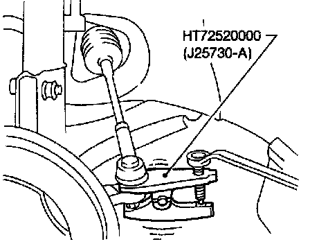
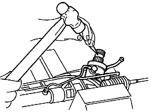
^ Detach tie-rod outer sockets from knuckle arms with Tool.
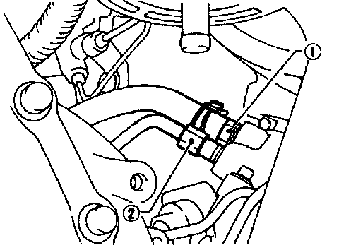
^ Install pipe connector.
^ Observe specified tightening torque when tightening high-pressure and low-pressure pipe connectors. Excessive tightening will damage threads of connector or 0-ring.
^ The 0-ring in low-pressure pipe connector is larger than that in high-pressure connector. Take care to install the proper 0-ring.
Connector tightening torque:
Low-pressure side "1" 21 - 39 N (2.8 - 4.0 kg, 20 - 29ft-lb)
High-pressure side "2" 15 - 25 N (1.5 - 2.5 kg, 11 - 18ft-lb)
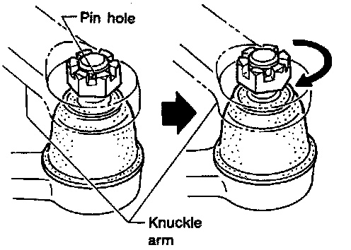
^ Initially, tighten nut on tie-rod outer socket and knuckle arm to 29 to 39 N (3 to 4 kg, 22 to 29 ft-lb). Then tighten further to align nut groove with first pin hole so that cotter pin can be installed.
CAUTION: Tightening torque must not exceed 49 N (5kg, 36ft-lb).
^ Before removing lower joint from gear, set gear in neutral (wheels in straight-ahead position). After removing lower joint, put matching mark on pinion shaft and pinion housing to record neutral position of gear.
^ To install, set left and right dust boots to equal deflection, and attach lower joint by aligning matching marks of pinion shaft and pinion housing.
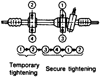
^ Tighten gear housing mounting bracket bolts in the order shown.
DISASSEMBLY
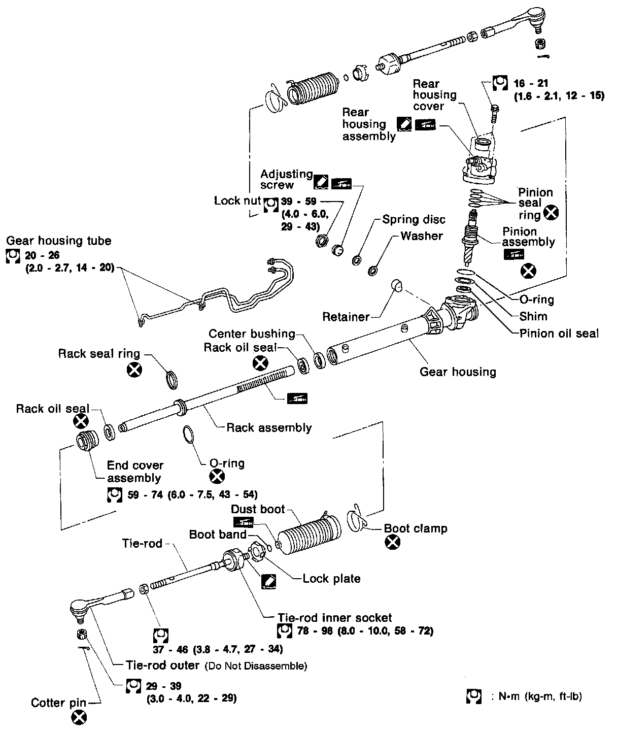
1. Prior to disassembling, measure pinion rotating torque. Record the pinion rotating torque as a reference.
^ Before measuring, disconnect gear housing tube and drain fluid.
^ Use soft jaws when holding steering gear housing. Handle gear housing carefully, as it is made of aluminum. Do not grip cylinder in a vise.
2. Remove pinion gear.
CAUTION: Be careful not to damage pinion gear when removing pinion seal ring.
3. Remove tie-rod outer sockets and boots.
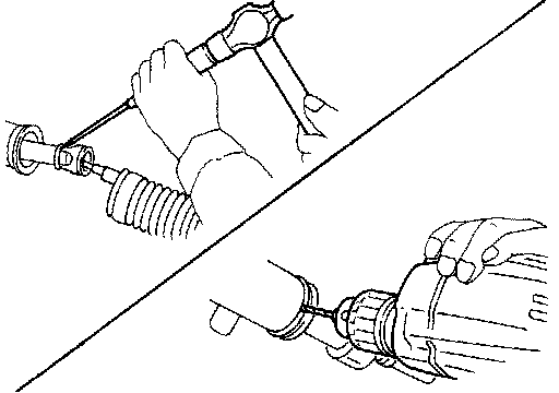
4. Loosen tie-rod inner socket by prying up staked portion, and remove socket.
5. Remove retainer.
6. Remove pinion assembly.
7. Drill staked portion of gear housing end with drill of 2 to 2.5mm (0.079 to 0.098in) diameter, until the staking is eliminated.
8. Remove end cover assembly with a suitable tool.
9. Draw out rack assembly.
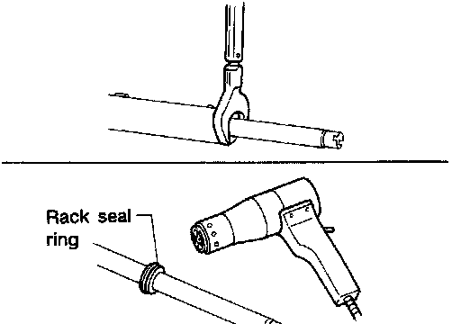
10. Remove rack seal ring.
^ Using a heat gun, heat rack seal to approximately 40°C (104°F).
^ Remove rack seal ring.
CAUTION: Be careful not to damage rack
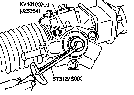
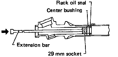
11. Remove center bushing and rack oil seal using tape wrapped socket and extension bar.
CAUTION: Do not scratch Inner surfaces of pinion housing.
INSPECTION
Thoroughly clean all parts in cleaning solvent or automatic transmission fluid type DEXRON(TM) II or equivalent, and blow dry with compressed air, if available.
Boot
Check condition of boot. If cracked excessively, replace it.
Rack
Thoroughly examine rack gear. If damaged, cracked or worn, replace it.
Pinion Assembly
^ Thoroughly examine pinion gear. If pinion gear is damaged, cracked or worn, replace it.
^ Inspect bearings to see that they roll freely and are free from cracked, pitted, or worn balls, rollers and races. Replace if necessary.
Gear Housing Cylinder
Check gear housing cylinder bore for scratches or other damage. Replace if necessary.
Tie-Rod Outer And Inner Sockets
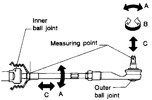
^ Check ball joints for swinging force.
Tie-rod outer ball joint:
At cotter pin hole (A):
6.9 - 64.7 N (0.7 - 6.6kg, 1.5 - 14.6lb)
Tie-rod inner ball joint (A):
14.7 - 215.8 N (1.5 - 22kg, 3.3 - 48.5lb)
^ Check ball joint for rotating torque.
Tie-rod outer ball joint (B):
0.3 - 2.9Nm (3 - 30kg, 2.6 - 26.0in lb)
^ Check ball joints for axial end play.
Tie-rod outer ball joint (C):
Less than 0.5mm (0.020in)
Tie-rod inner ball joint (C):
0mm (0in)
^ Check condition of dust cover. If cracked excessively, replace.
ASSEMBLY
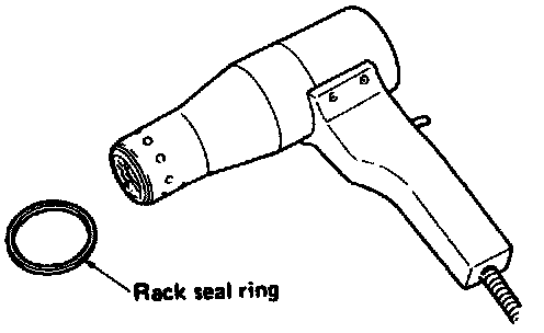
1. Using a heat gun, heat new rack seal ring (made of Teflon) to approximately 4O°C (1O4°F) and install it onto rack with your hand.
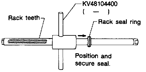
2. Using Tool, compress periphery of rack seal ring to position and secure it on rack.
NOTE: Always Insert Tool from the rack gear side.
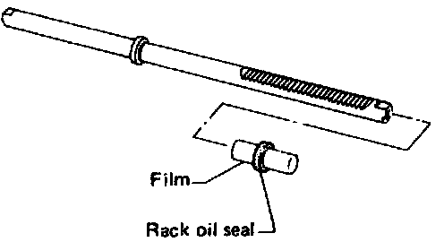
3. Insert new rack oil seal.
^ Place plastic film into rack oil seal to prevent damage by rack teeth.
^ Do not forget to remove plastic film after rack oil seal is positioned properly.
^ Make sure lips of rack oil seal face each other.
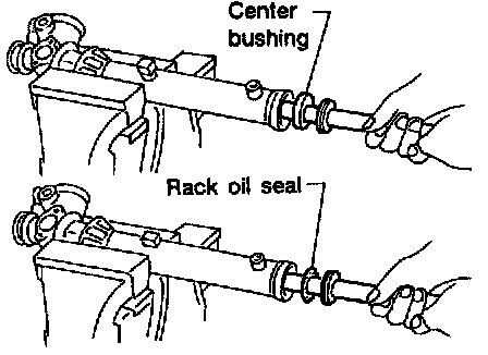
4. Install center bushing and rack oil seal with rack assembly.
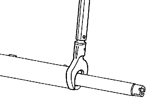
5. Tighten end cover assembly with a suitable tool.

6. Fasten end cover assembly to gear housing by staking.
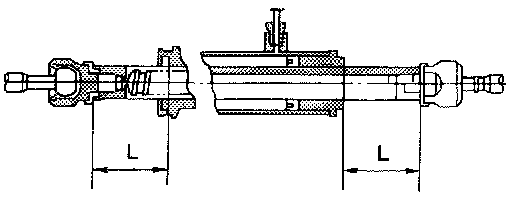
7. Set rack gear in neutral position.
Rack stroke:
For vehicle with GA16DE engine:
73.5mm (2.894in)
For vehicle with SR20DE engine:
65.5mm (2.579in)
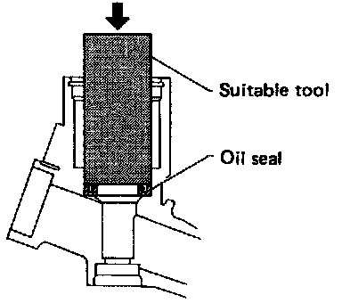
8. Coat seal lip of new pinion oil seal with multi-purpose grease and install it to pinion housing of gear housing with a suitable tool.
NOTE: Make sure lip of oil seal faces up when Installed.
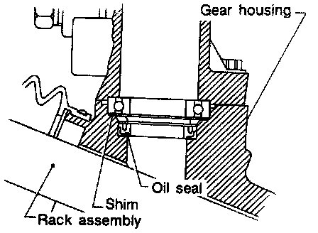
9. Install pinion bearing adjusting shim(s).
^ Whenever pinion assembly, gear housing and rear housing are disassembled, replace shim(s) with new ones. Always use the same number of shim(s) when replacing.
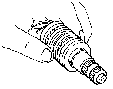
10. Install new pinion seal ring (made of Teflon) on pinion gear assembly.
^ Using a heat gun, heat pinion seal ring to approximately 40°C (104°F) before installing it onto pinion gear assembly.
^ Make sure pinion seal ring is properly settled in valve groove.
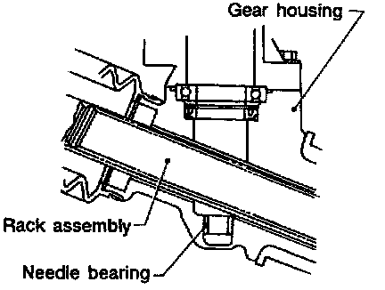
11. Apply a coat of multi-purpose grease to needle bearing roller and oil seal lip before installing pinion assembly in gear housing.
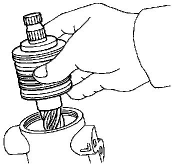
12. Install pinion assembly to pinion housing.
NOTE: Be careful not to damage pinion oil seal.
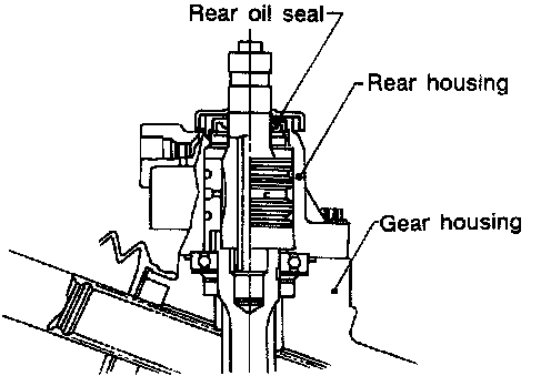
13. Apply a coat of multi-purpose grease to new rear oil seal lip before installing rear housing.
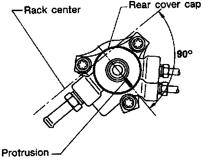
14. Install rear cover cap so that protrusion of rear housing cover is positioned as shown in figure at left when rack is centralized.
NOTE: Be careful not to damage worm ring and oil seal.
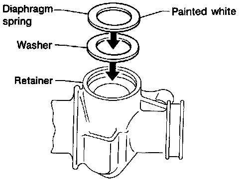
15. Install diaphragm spring into gear housing.
^ Always install retainer, spring washer and diaphragm spring in that order.
^ Make sure convex end (painted white) of diaphragm spring faces outward when installing.
16. Install retainer and adjusting screw temporarily.
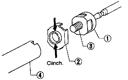
17. Install new lock plate.
^ Attach lock plate (2) to tie-rod inner socket (1).
^ Apply locking sealant to inner socket threads (3) Screw inner socket into rack (4) and tighten to specified torque.
^ Clinch two places of lock plate at rack's groove.
CAUTION: To prevent scratching the boot, remove burrs from lock plate.
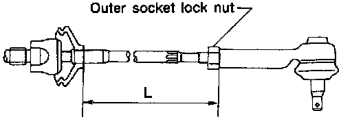
18. Tighten outer socket lock nut.
Tie-rod length (L):
184mm (7.24in)
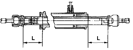
19. Measure rack stroke.
Rack stroke (L):
For vehicle with GA16DE engine:
73.5mm (2.894in)
For vehicle with SR20DE engine:
65.5mm (2.579in)
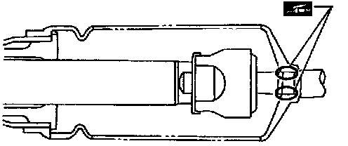
20. Before installing boot, coat the contact surfaces between boot and tie-rod with grease.
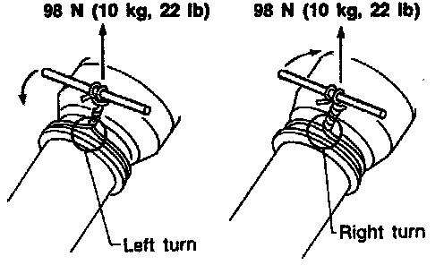
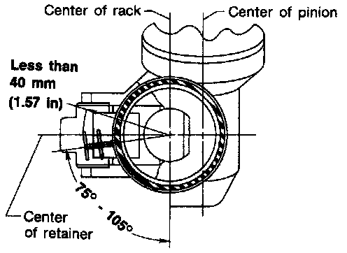
21. Install boot clamps.
^ To install, wrap boot clamp around boot groove twice. Tighten clamp by twisting rings at both ends 4 to 4-1/2 turns with screwdriver while pulling with a force of approximately 98 N (10 kg, 22 lb).
^ Twist boot clamp in the direction shown in figure at left.
^ Install boot clamps so they are behind the gear housing when it is attached to the vehicle. (This will prevent interference with other parts.)
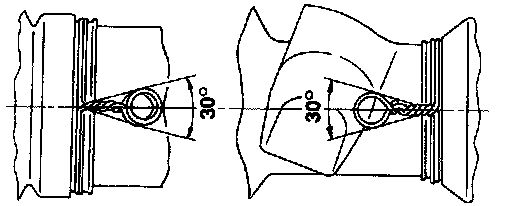
^ After twisting boot clamp, bend twisted and diagonally so it does not contact boot.
ADJUSTMENT
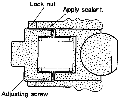
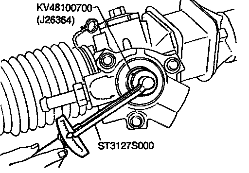
Adjust pinion rotating torque as follows:
1. Set rack to the neutral position without fluid in the gear.
2. Coat the adjusting screw with locking sealant and screw it in.
3. Lightly tighten lock nut.
4. Tighten adjusting screw to a torque of 4.9 to 5.9 N (50 to 60kg-cm, 43 to 52in-lb).
5. Loosen adjusting screw, then retighten it to 0.2 N (2kg-cm, 1.7in-lb).
6. Move rack over its entire stroke several times.
7. Measure pinion rotating torque within the range of 180° from neutral position. Stop the gear at the point of maximum torque.
8. Loosen adjusting screw, then retighten it to 4.9 N (50kg-cm, 43in-lb).
9. Loosen adjusting screw by 40° to 60°.
10. Prevent adjusting screw from turning, and tighten lock nut to specified torque.
11. Measure pinion rotating torque.
Within ±100° from the neutral position:
Average rotating torque 0.8 - 1.3 N (8 - 13kg-m, 6.9 - 11.3in-lb)
Maximum torque deviation 0.4 N (4kg-cm, 3.5in-lb)
Except for above measuring range:
Maximum rotating torque 1.9 N (19kg-cm, 16in-lb)
Maximum force deviation 0.6 N (6kg-cm, 5.2in-lb)
^ If pinion rotating torque is not within specifications, readjust it starting from procedure 4. If pinion rotating torque is still out of specifications after readjustment, replace steering gear assembly.
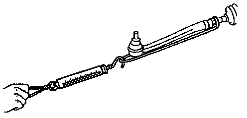
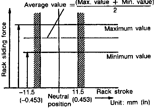
12. Check rack sliding force on vehicle as follows:
a. Install steering gear onto vehicle, but do not connect tie-rod to knuckle arm.
b. Connect all piping and fill with steering fluid.
c. Start engine and bleed air completely.
d. Disconnect steering column lower joint from the gear.
e. Keep engine at idle and make sure steering fluid has reached normal operating temperature.
f. While pulling tie-rod slowly in the ±11.5 mm (±0.453 in) range from the neutral position, make sure rack sliding force is within specification.
Average rack sliding force:
Less than 226 N (23kg, 51lb)
g. Check sliding force outside above range.
Maximum rack sliding force:
Not more than 98 N (10kg, 22lb) beyond above value.
^ If rack sliding force is not within specification, readjust by repeating adjustment procedure from the beginning.
^ If rack sliding force is still out of specification after readjustment, gear assembly needs to be replaced.