Part 1
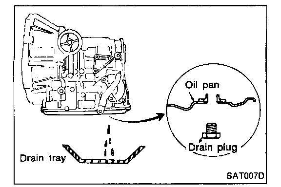
1. Drain A.T.F. through drain plug.
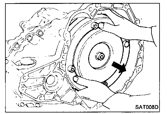
2. Remove torque converter.
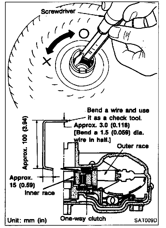
3. Check torque converter one-way clutch using check tool as shown at left.
a. Insert check tool into the groove of bearing support built into one-way clutch outer race.
b. While fixing bearing support with check tool, rotate one-way clutch spline using flat-bladed screwdriver.
c. Check inner race rotates clockwise only. If not, replace torque converter assembly.
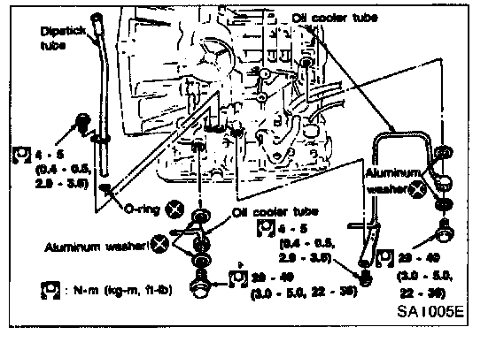
4. Remove oil charging pipe and oil cooler tube.
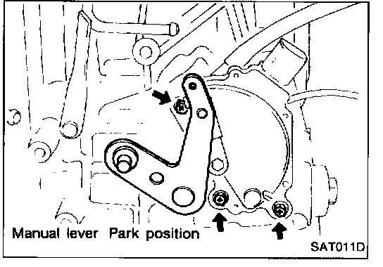
5. Set manual lever to �P" position.
6. Remove inhibitor switch.
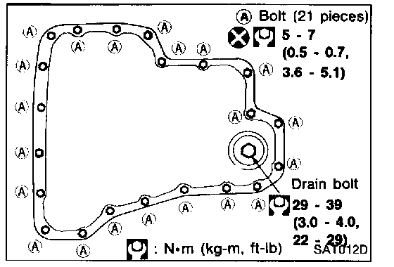
7. Remove oil pan and oil pan gasket.
- Do not reuse oil pan bolts.
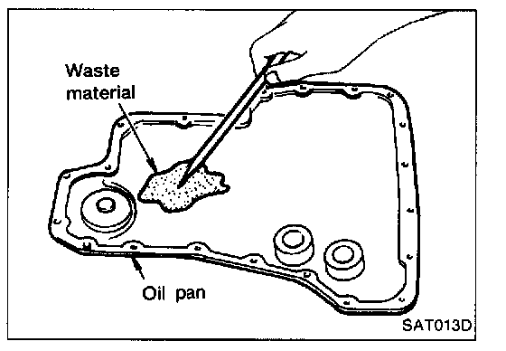
8. Check foreign materials in oil pan to help determine cause of malfunction. If the fluid is very dark, smells burned, or contains foreign particles, the frictional material (clutches, band) may need replacement. A tacky film that will not wipe clean indicates varnish build up which can cause valves, servo, and clutches to stick and may inhibit pump pressure.
9. Remove control valve assembly according to the following procedures.
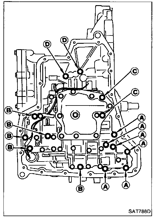
a. Remove control valve assembly mounting bolts (A), (B), (C) and (D).
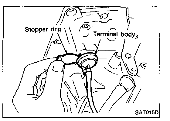
b. Remove stopper ring from terminal body.
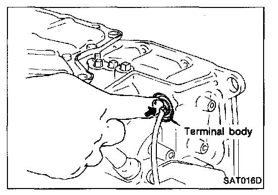
c. Push terminal body into transmission case and draw out solenoid harness.
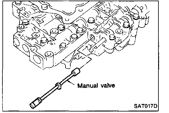
10. Remove manual valve from control valve assembly as a precaution.
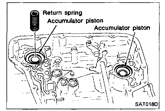
11. Remove return spring from 3-R accumulator piston.
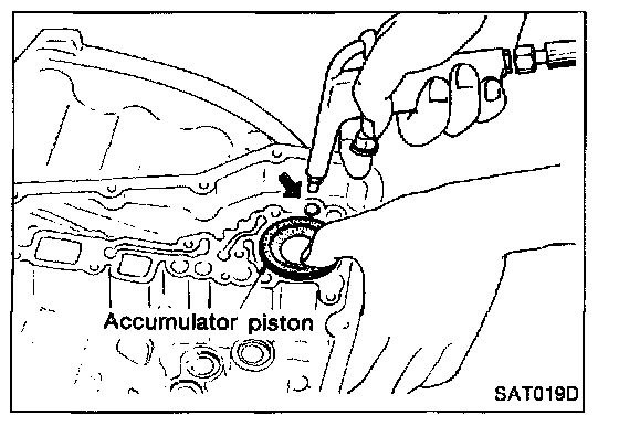
12. Remove 3-R accumulator piston with compressed air.
13. Remove O-rings from 3-R accumulator piston.
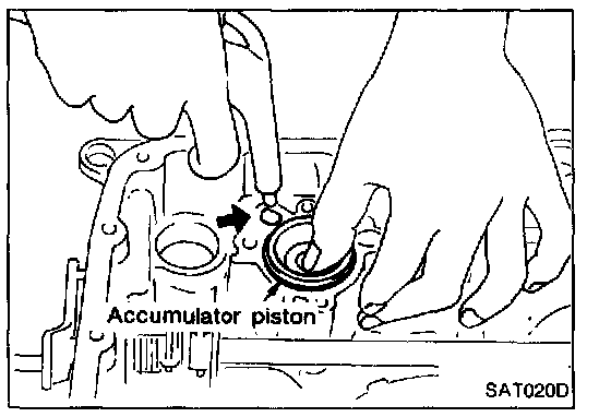
14. Remove N-D accumulator piston and return spring with compressed air.
15. Remove O-rings from N-D accumulator piston.
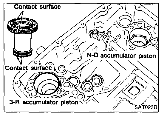
16. Check accumulator pistons and contact surface of transmission case for damage.
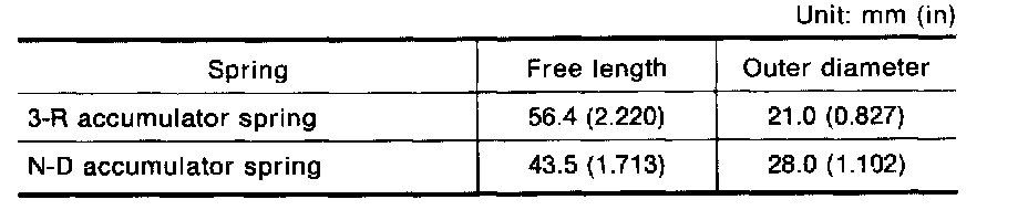
17. Check accumulator return springs for damage and free length.
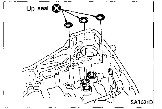
18. Remove lip seals from band servo oil port.
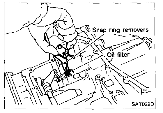
19. Remove oil filter for governor.
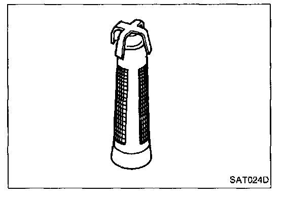
20. Check oil filter for governor for damage or clogging.
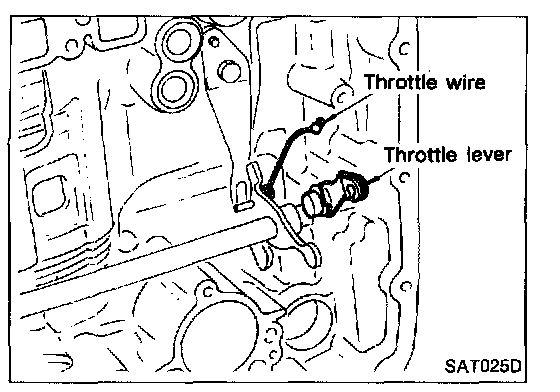
21. Remove throttle wire from throttle lever.
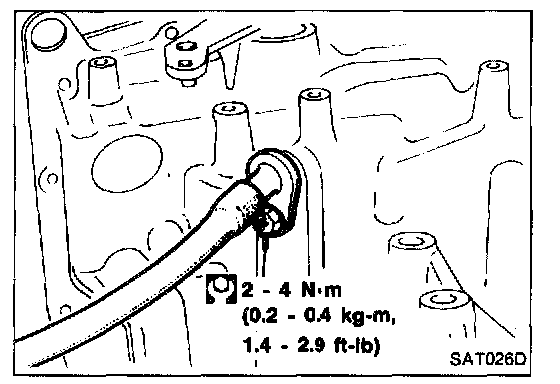
22. Remove throttle wire mounting bolt.
23. Draw out throttle wire from transmission case.
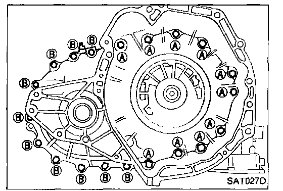
24. Remove converter housing according to the following procedures.
a. Remove converter housing mounting bolts (A) and (B).
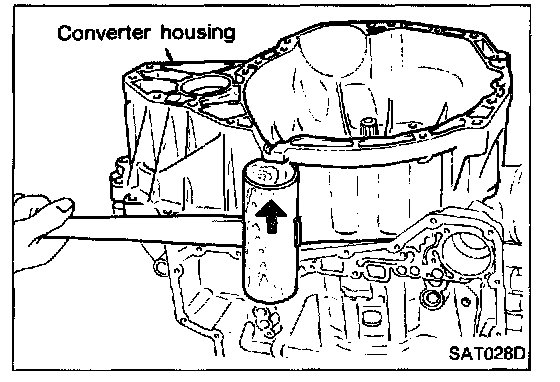
b. Remove converter housing.
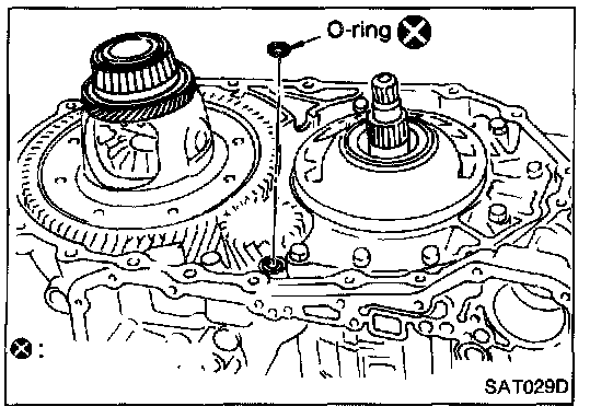
c. Remove O-ring from differential oil port.
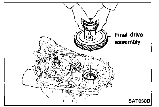
25. Remove final drive assembly from transmission case.
If it is difficult to lift up by hand, tap final drive slightly with a soft hammer (RL4F03A).
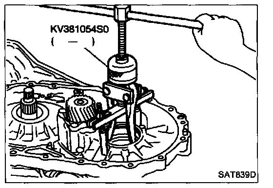
26. Remove differential side bearing outer race from transmission case (RL4F03V).
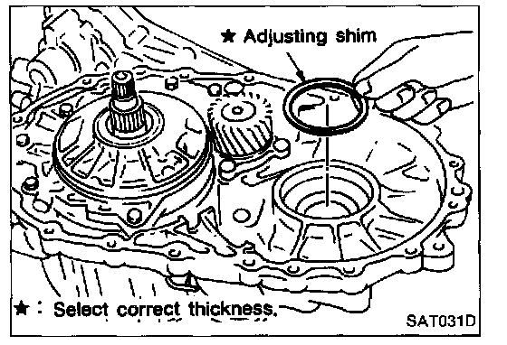
27. Remove differential side bearing adjusting shim from transmission case.
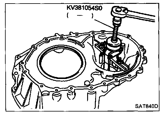
28. Remove differential side bearing outer race from converter housing (RL4F03V).
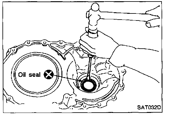
29. Remove oil seal from converter housing using a screwdriver.
- Be careful not to damage case.
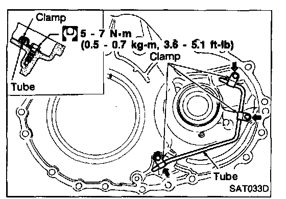
30. Remove oil tube from converter housing.
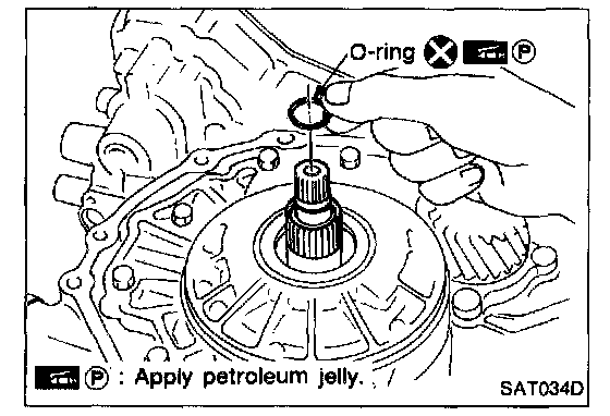
31. Remove oil pump according to the following procedures.
a. Remove O-ring from input shaft.
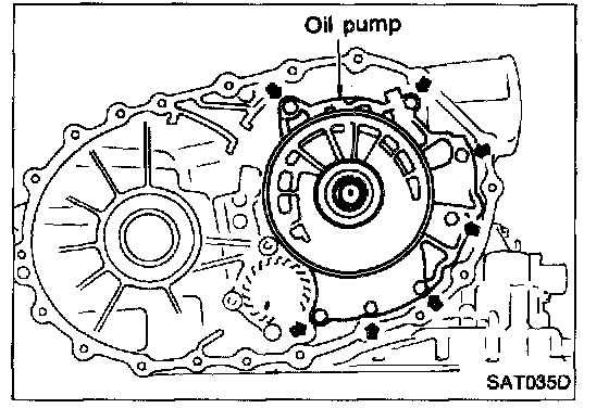
b. Remove oil pump assembly from transmission case.
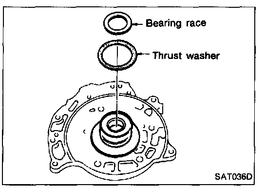
c. Remove thrust washer and bearing race from oil pump assembly.
32. Remove brake band according to the following procedures.
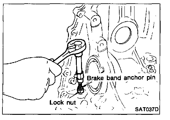
a. Loosen lock nut, then back off band servo anchor end pin.
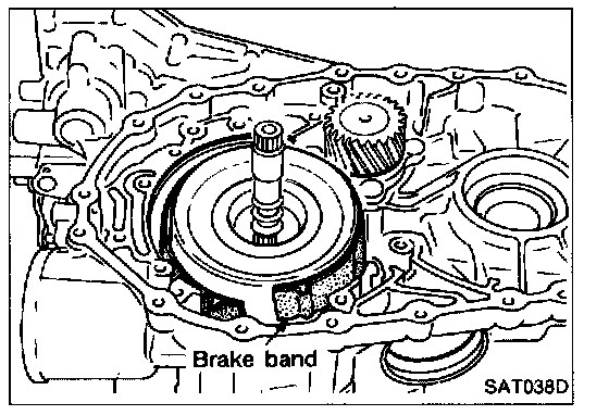
b. Remove brake band from transmission case.
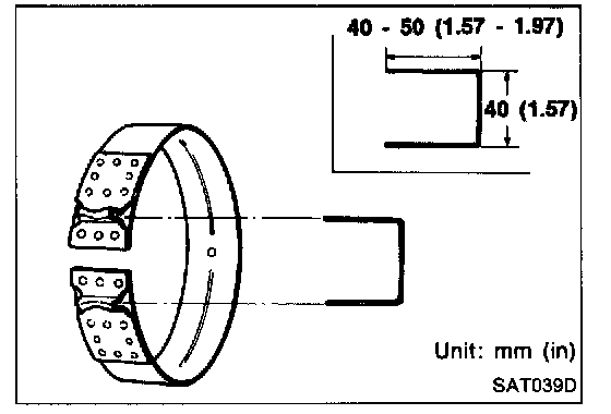
- To prevent brake linings from cracking or peeling, do not stretch the flexible band unnecessarily. When removing the brake band, always secure it with a clip as shown in the figure at left.
Leave the clip in position after removing the brake band.
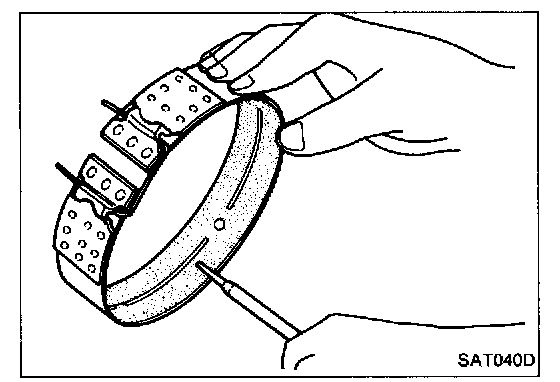
c. Check brake band facing for damage, cracks, wear or burns.
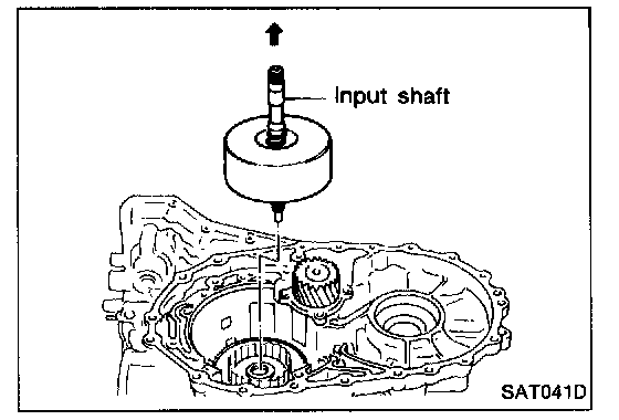
33. Remove input shaft assembly (high clutch) and reverse clutch according to the following procedures.
a. Remove input shaft assembly (high clutch) with reverse clutch.
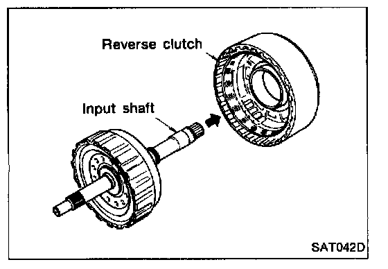
b. Remove input shaft assembly (high clutch) from reverse clutch.
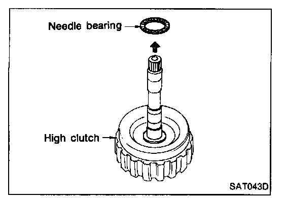
c. Remove needle bearing from high clutch drum.
d. Check input shaft assembly and needle bearing for damage or wear.
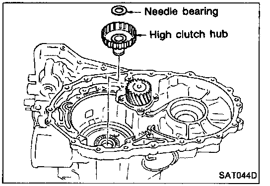
34. Remove high clutch hub and needle bearing from transmission case.
35. Check high clutch hub and needle bearing for damage or wear.
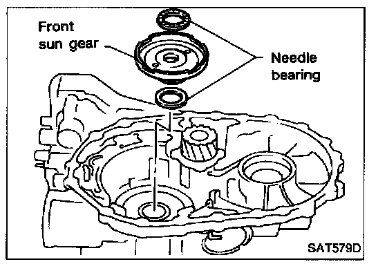
36. Remove front sun gear and needle bearings from transmission case.
37. Check front sun gear and needle bearings for damage or wear.
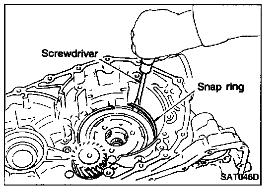
38. Remove front planetary carrier assembly and low one-way clutch according to the following procedures.
a. Remove snap ring using a screwdriver.
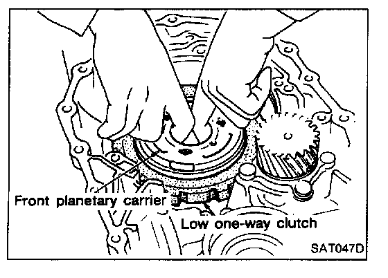
b. Remove front planetary carrier with low one-way clutch.
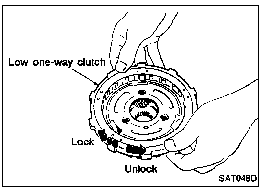
c. Check that low one-way clutch rotates in the direction of the arrow and locks in the opposite direction.
d. Remove low one-way clutch from front planetary carrier by rotating it in the direction of unlock.
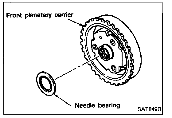
e. Remove needle bearing from front planetary carrier.
f. Check front planetary carrier, low one-way clutch and needle bearing for damage or wear.
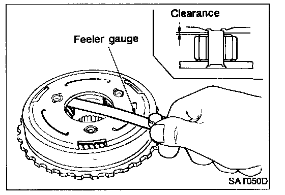
g. Check clearance between pinion washer and planetary carrier using feeler gauge.
Standard clearance: 0.15 - 0.70 mm (0.0059 - 0.0276 in.)
Replace if the clearance exceeds 0.80 mm (0.0315 in.).
39. Remove rear planetary carrier assembly and rear sun gear according to the following procedures.
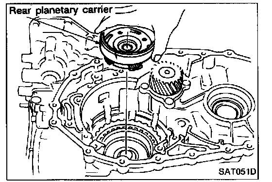
a. Remove rear planetary carrier assembly from transmission case.
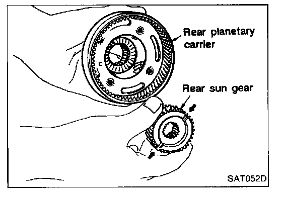
b. Remove rear sun gear from rear planetary carrier.
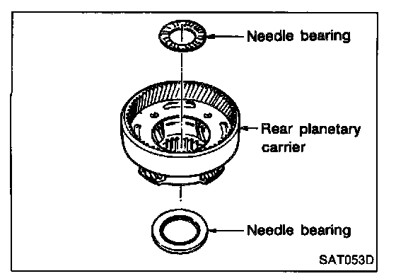
c. Remove needle bearings from rear planetary carrier assembly.
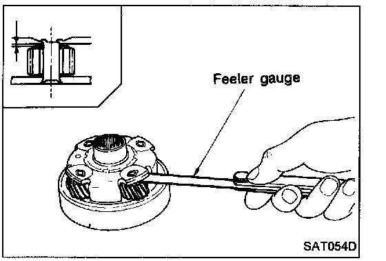
d. Check rear planetary carrier, rear sun gear and needle bearings for damage or wear.
e. Check clearance between pinion washer and rear planetary carrier using feeler gauge.
Standard clearance: 0.15 - 0.70 mm (0.0059 - 0.0276 in.)
Replace if the clearance exceeds 0.80 mm (0.031 in.).
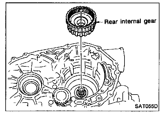
40. Remove rear internal gear from transmission case.
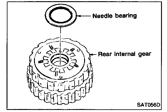
41. Remove needle bearing from rear internal gear.
42. Check needle bearing for damage or wear.
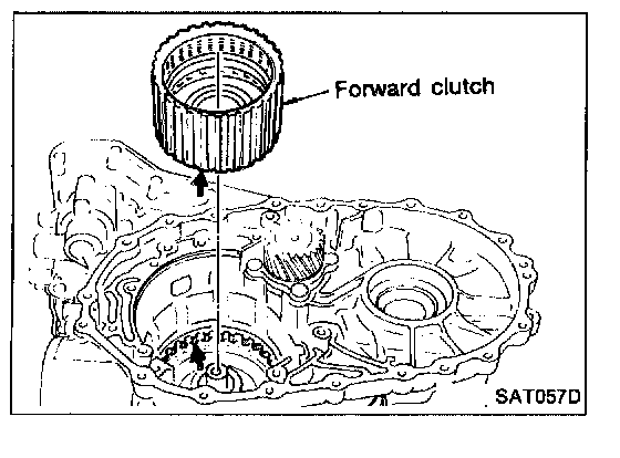
43. Remove forward clutch assembly from transmission case.
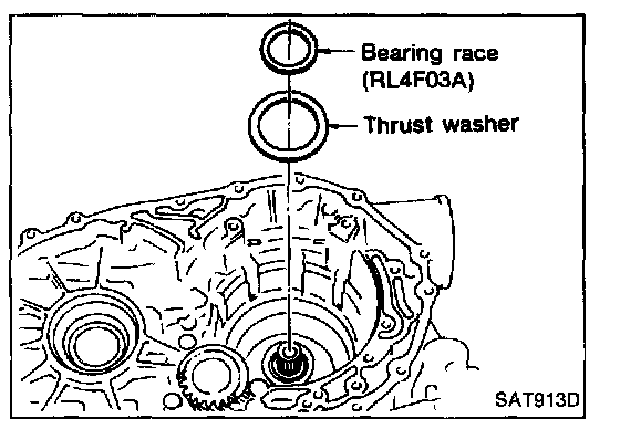
44. Remove thrust washer and bearing race (only RL4F03A) from transmission case.