Part 3
ADJUSTMENTFINAL DRIVE END PLAY - RL4F03A
- Measure clearance between differential side bearing and transmission case.
- Select proper thickness of adjusting shim so that end play is within specifications.
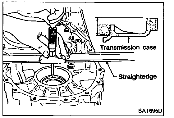
1. Measure dimension "T" between side bearing fitting surface of transmission case and converter housing fitting surface of transmission case.
"T(1)": Indication of gauge
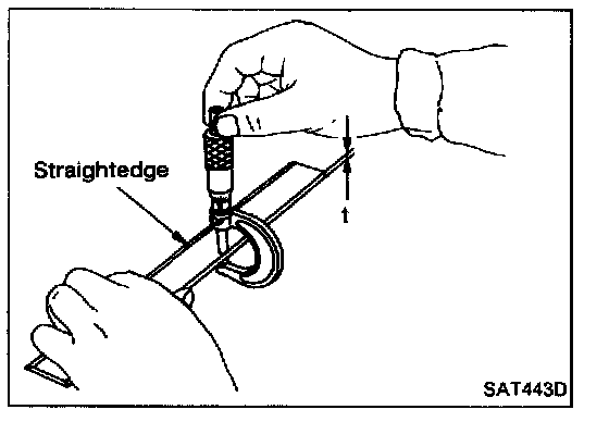
2. Measure thickness of straightedge "t".
T = T(1) - t
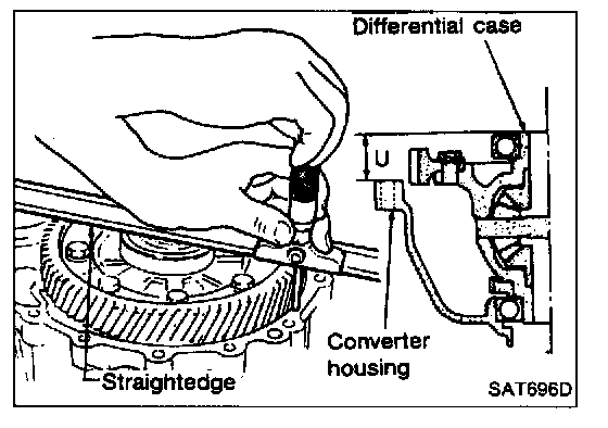
3. Place final drive assembly on converter housing.
4. Measure dimension "U" between end of differential case and transmission case fitting surface of converter housing.
5. Measure dimension "V" between end of differential case and adjusting shim mating surface of differential side bearing.
6. Calculate final drive end play.
Final drive end play: T - U + V
7. Select proper thickness of differential side bearing adjusting shim so that final drive end play is within specifications.
Final drive end play: 0 - 0.15 mm (0 - 0.0059 in.)
Differential side bearing adjusting shim: Refer to Specifications.
ASSEMBLY
1. Install differential side bearing adjusting shim selected in final drive end play adjustment step on transmission case (only RL4F03A).
2. Install final drive assembly on transmission case.
3. Install oil tube on converter housing.
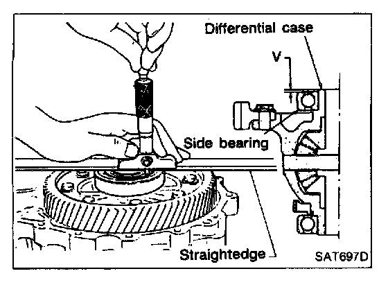
5. Measure dimension "V" between end of differential case and adjusting shim mating surface of differential side bearing.
6. Calculate final drive end play.
Final drive end play: T - U + V
7. Select proper thickness of differential side bearing adjusting shim so that final drive end play is within specifications.
Final drive end play: 0 - 0.15 mm (0 - 0.0059 in.)
Differential side bearing adjusting shim: Refer to Specifications.
ASSEMBLY
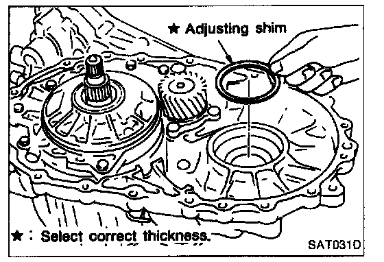
1. Install differential side bearing adjusting shim selected in final drive end play adjustment step on transmission case (only RL4F03A).
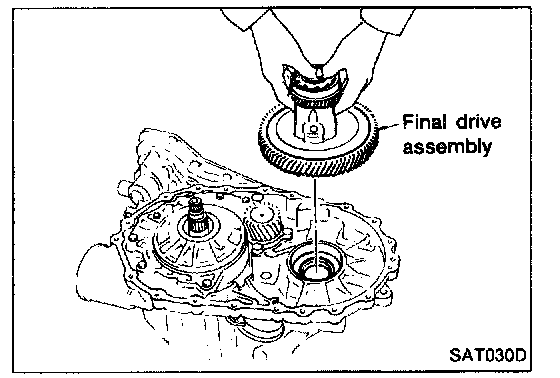
2. Install final drive assembly on transmission case.
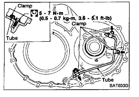
3. Install oil tube on converter housing.
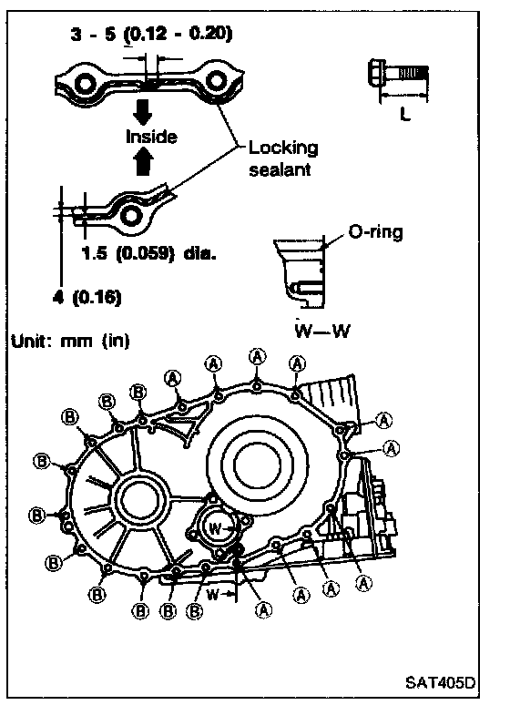
4. Install O-ring on differential oil port of transmission case.
5. Install converter housing on transmission case.

- Apply locking sealant to mating surface of converter housing.
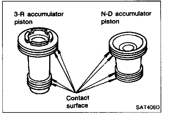
6. Install accumulator piston.
a. Check contact surface of accumulator piston for damage.
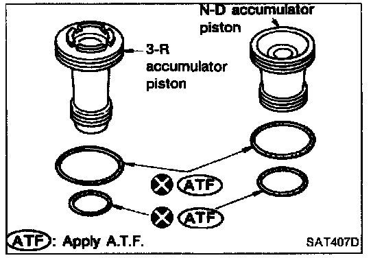
b. Install O-rings on accumulator piston.
Accumulator Piston O-rings:
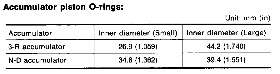
- Apply A.T.F. to O-rings.
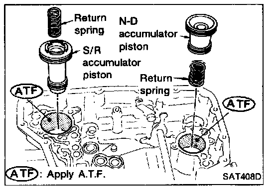
c. Install accumulator pistons and return springs on transmission case.
Return Springs:
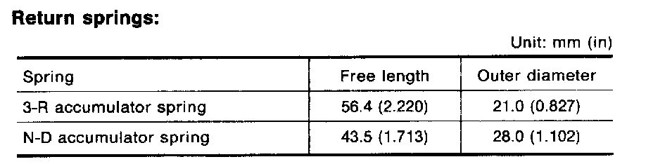
- Apply A.T.F. to inner surface of transmission case.
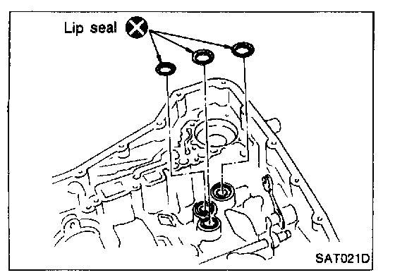
7. Install lip seals for band servo oil holes on transmission case.
- Apply petroleum jelly to lip seals.
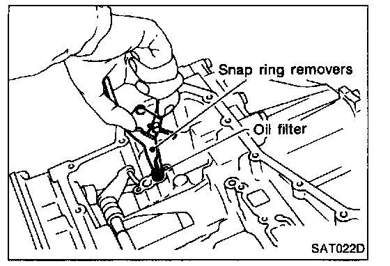
8. Install oil filter for governor valve.
- Take care with its direction.
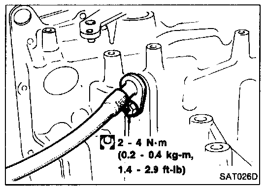
9. Install throttle wire to transmission case.
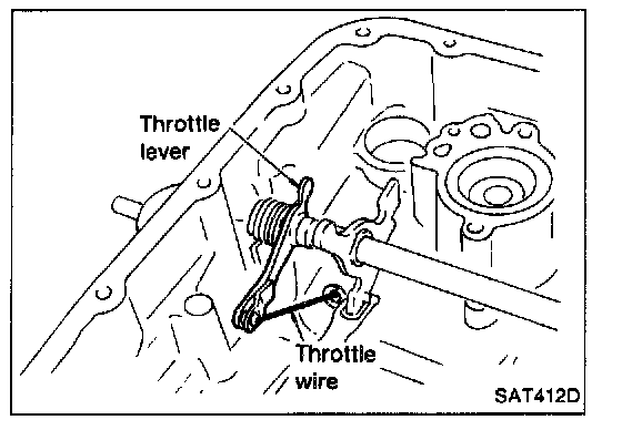
10. Install throttle wire to throttle lever.
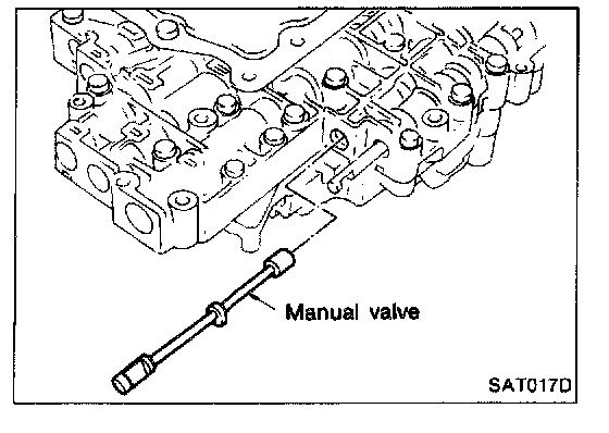
11. Install control valve assembly.
a. Insert manual valve into control valve assembly.
- Apply A.T.F. to manual valve.
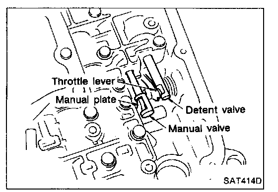
b. Set manual shaft in Neutral position.
c. Install control valve assembly on transmission case while aligning manual valve with manual plate and detent valve with throttle lever.
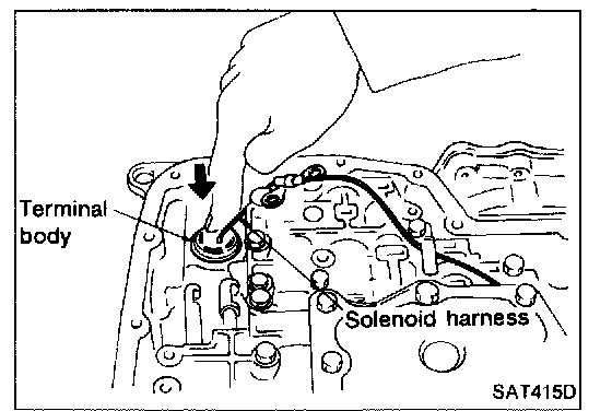
d. Pass solenoid harness through transmission case and install terminal body on transmission case by pushing it.
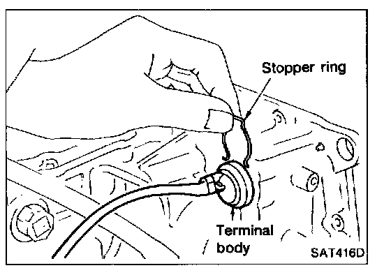
e. Install clip to terminal body.
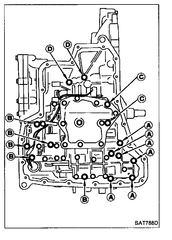
Bolt Length, Number And Location:
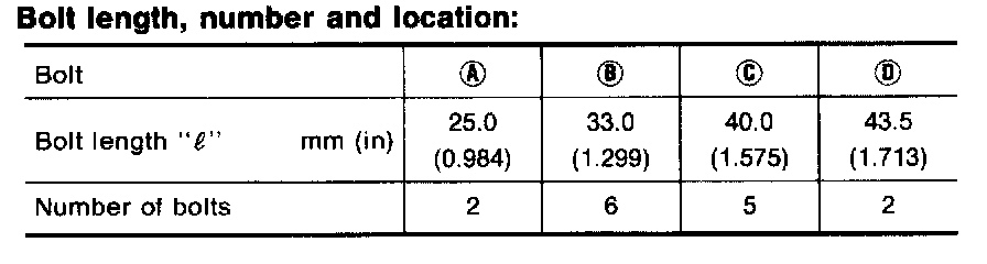
f. Tighten bolts (A), (B), (C) and (D).
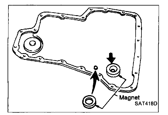
12. Install oil pan.
a. Attach magnet to oil pan.
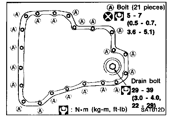
b. Install new oil pan gasket on transmission case.
c. Install oil pan on transmission case.
- Always replace oil pan bolts as they are self-sealing bolts.
- Tighten the four bolts in a criss-cross pattern to prevent dislocation of gasket.
d. Tighten drain plug to specified torque.
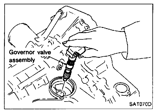
13. Install governor valve.
a. Install governor valve assembly into transmission case.
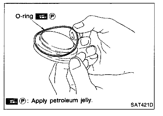
b. Install O-ring to governor cap.
- Apply A.T.F. to O-ring.
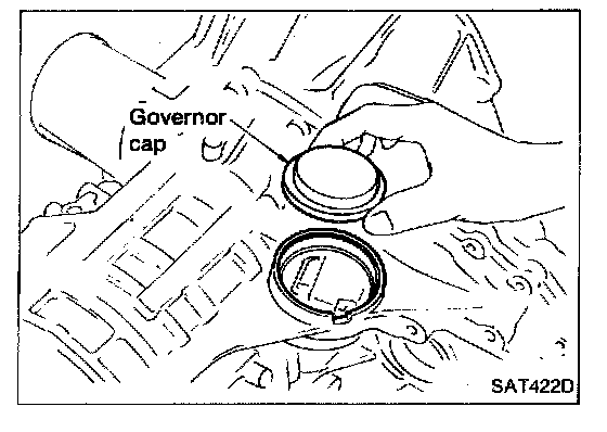
c. Install governor cap onto transmission case.
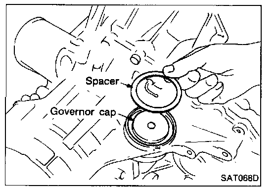
d. Place spacer on governor cap.
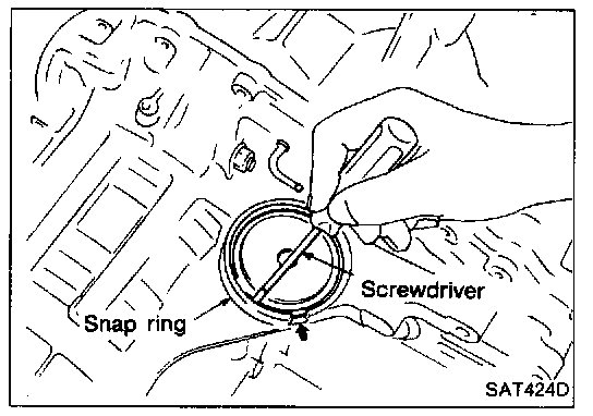
e. Install snap ring onto transmission case with a screwdriver.
- Align snap ring gap with the notch of transmission case.
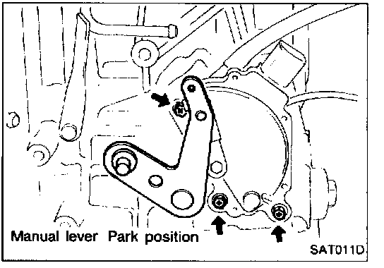
14. Install inhibitor switch.
a. Set manual lever in "P" position.
b. Temporarily install inhibitor switch on manual shaft.
c. Move selector lever to "N" position.
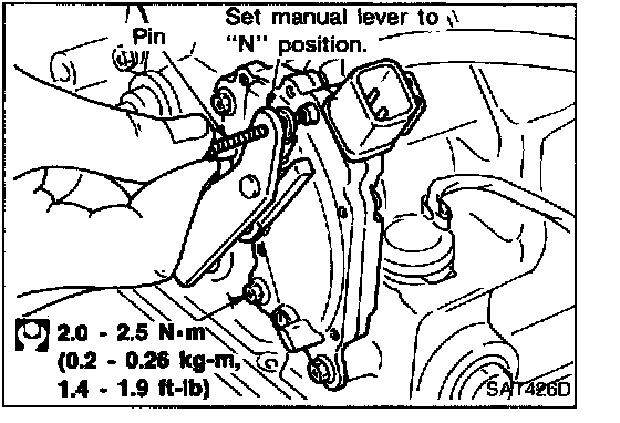
d. Insert 4.0 mm (0.157 in.) dia. pin into adjustment hole in both inhibitor switch and manual shaft as near vertically as possible.
e. Tighten inhibitor switch fixing bolts.
f. Remove pin from adjustment hole after adjusting inhibitor switch.
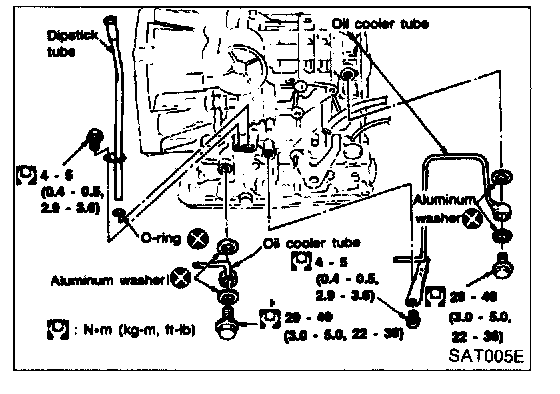
15. Install oil charging pipe and oil cooler tube to transmission case.
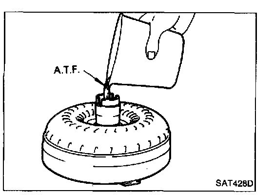
16. Install torque converter.
a. Pour A.T.F. into torque converter.
- Approximately 1 liter (1 - 1/8 US qt, 7/8 Imp qt) of fluid is required for a new torque converter.
- When reusing old torque converter, add the same amount of fluid as was drained.
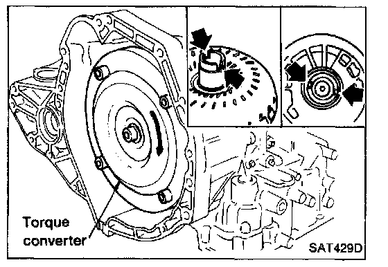
b. Install torque converter while aligning notches of torque converter with notches of oil pump.
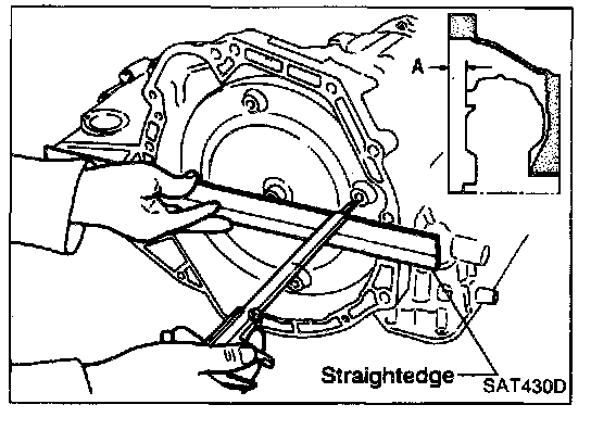
c. Measure distance "A" to check that torque converter is in proper position.
Distance "A":
GA engine models 21.1 mm (0.831 in.) or more
SR engine models 15.9 mm (0.626 in.) or more