Part 1
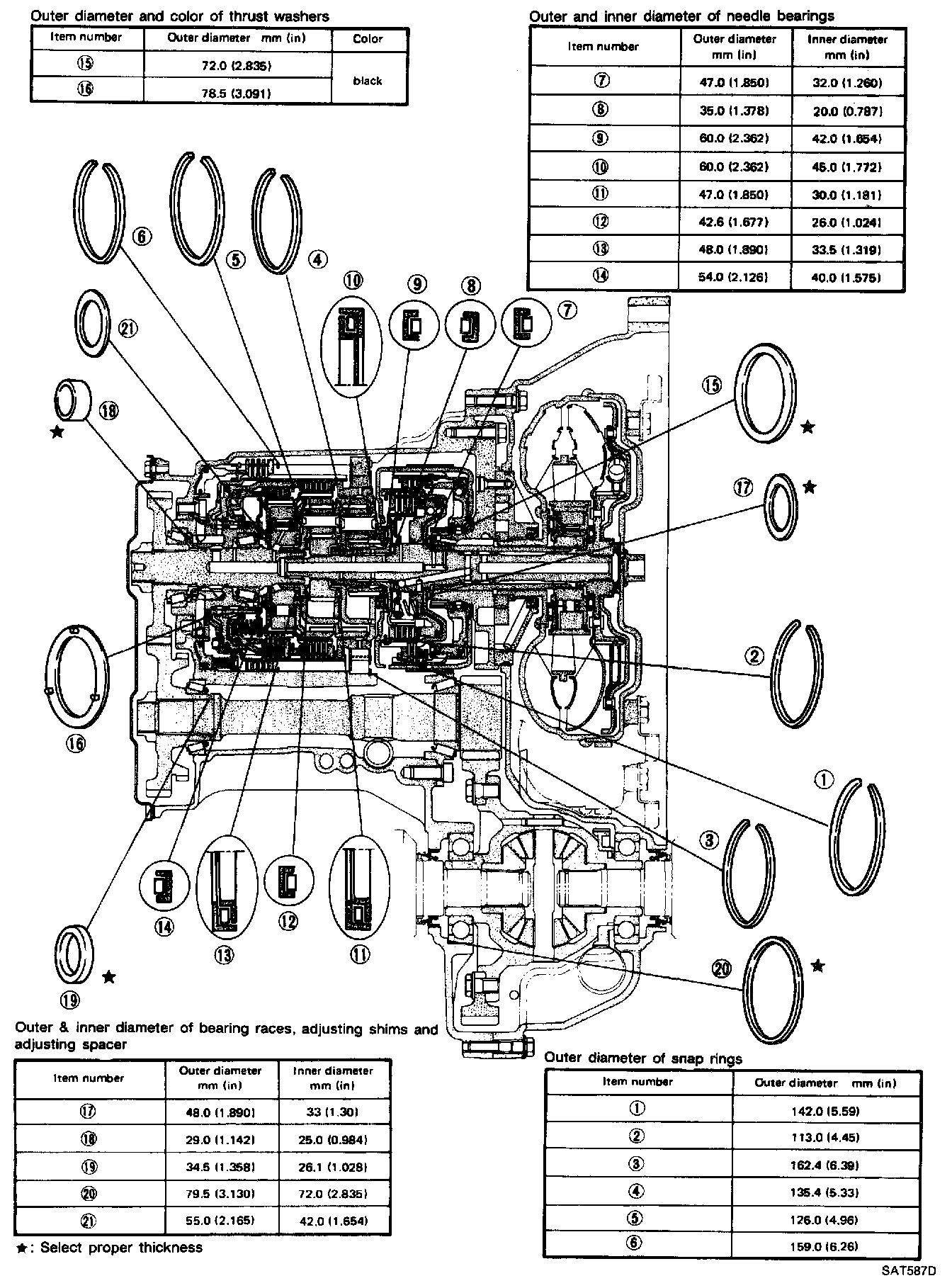
Locations Of Adjusting Shims, Needle Bearings, Thrust Washers And Snap Rings - RL4F03A:
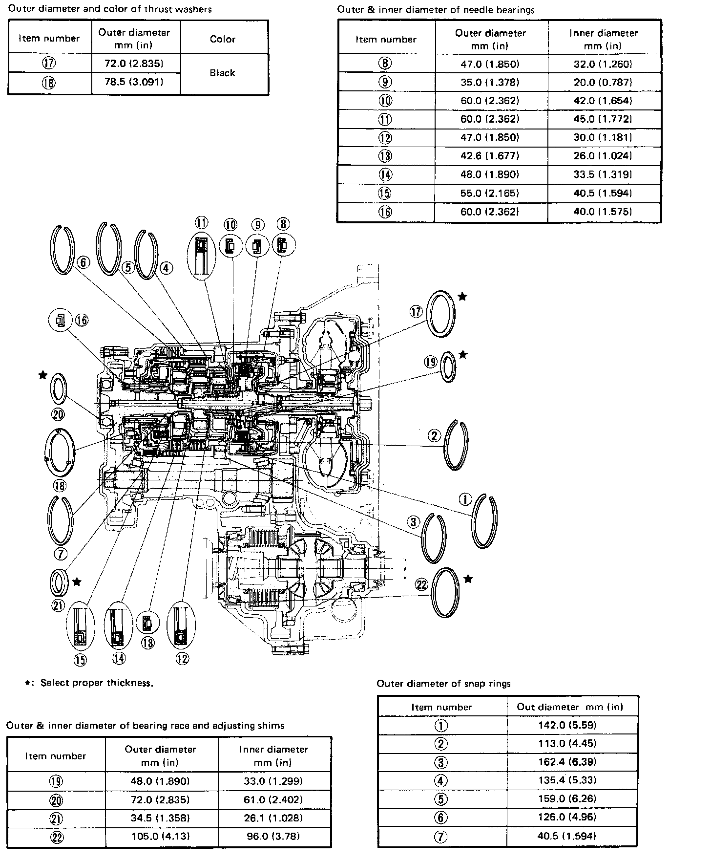
Locations Of Adjusting Shims, Needle Bearings, Thrust Washers And Snap Rings - RL4F03V:
ASSEMBLY
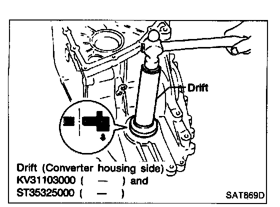
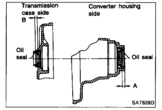
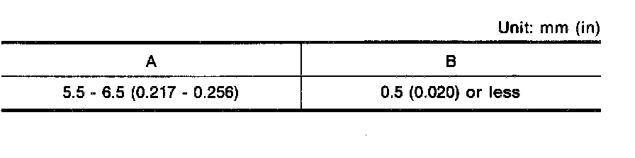
1. Install differential side oil seals on transmission case and converter housing, so that "A" and "B" are within specifications.
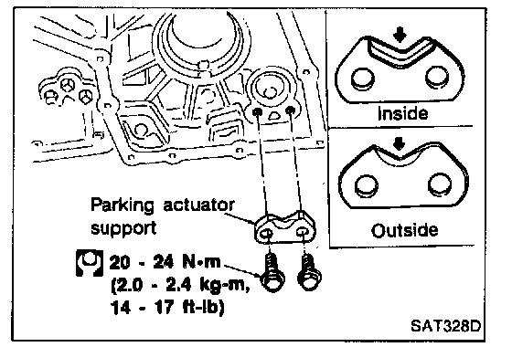
2. Install parking actuator support to transmission case.
- Pay attention to direction of parking actuator support.
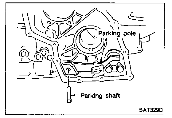
3. Install parking pawl on transmission case and fix it with parking shaft.
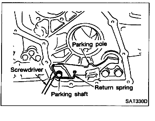
4. Install return spring.
ADJUSTMENT
DIFFERENTIAL SIDE BEARING PRELOAD - RL4F03V
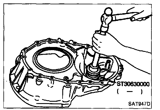
1. Install differential side bearing outer race without adjusting shim on transmission case.
2. Install differential side bearing outer race on converter housing.
3. Place final drive assembly on transmission case.
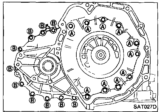
4. Install transmission case on converter housing and tighten transmission case fixing bolts (A) and (B) to the specified torque.
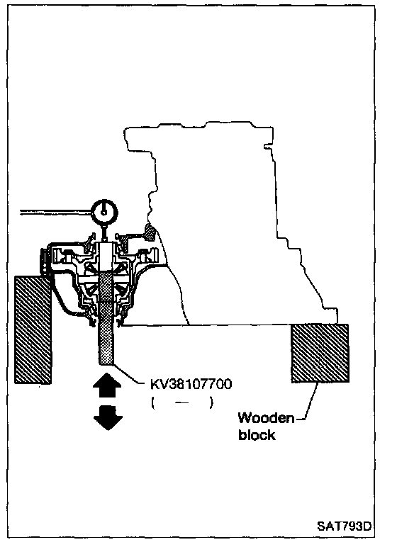
5. Attach dial indicator on differential case at transmission case side.
6. Insert Tool into differential side gear from converter housing.
7. Move Tool up and down and measure dial indicator deflection.
8. Select proper thickness of differential side bearing adjusting shim(s) using Specifications. table as a guide.
Differential side bearing adjusting shim: Refer to Specifications.
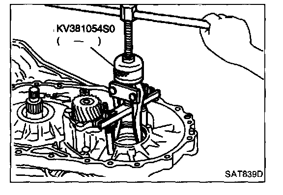
9. Remove converter housing from transmission case.
10. Remove final drive assembly from transmission case.
11. Remove differential side bearing outer race from transmission case.
12. Reinstall differential side bearing outer race and shim(s) selected from Specifications. table on transmission case.
13. Reinstall converter housing on transmission case and tighten transmission case fixing bolts to the specified torque.
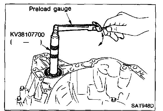
14. Insert Tool into differential case and measure turning torque of final drive assembly.
- When measuring turning torque, turn final drive assembly in both directions several times to seat bearing rollers correctly.
Turning torque of final drive assembly (New bearing): 0.49 - 1.08 N.m (5.0 - 11.0 kg-cm, 4.3 - 9.5 in-lb)
- When old bearing is used again, turning torque will be slightly less than the above.
- Make sure torque is close to the specified range.
REDUCTION GEAR BEARING PRELOAD
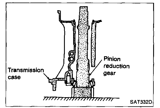
1. Remove transmission case and final drive assembly from converter housing.
2. Select proper thickness of reduction gear bearing adjusting shim using the following procedures.
a. Place reduction gear on transmission case as shown.
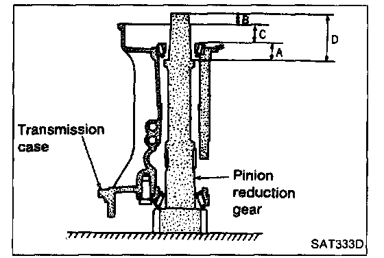
b. Place idler gear bearing on transmission case.
c. Measure dimensions "B" "C" and "D" and calculate dimension "A".
- "A": Distance between the surface of idler gear bearing inner race and the adjusting shim mating surface of reduction gear.
A = D - (B + C)
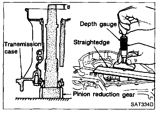
- Measure dimension "B" between the end of reduction gear and the surface of transmission case.
- Measure dimension "B" in at least two places.
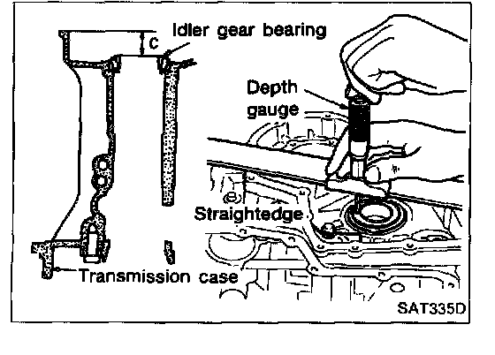
- Measure dimension "C" between the surface of idler gear bearing inner race and the surface of transmission case.
- Measure dimension "C" in at least two places.
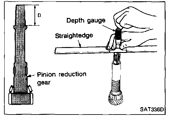
- Measure dimension "D" between the end of reduction gear and the adjusting shim mating surface of reduction gear.
- Measure dimension "D" in at least two places.
- Calculate dimension "A"
A = D - (B + C)
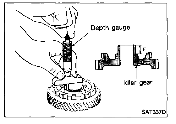
d. Measure dimension "E" between the end of idler gear and the idler gear bearing inner race mating surface of idler gear.
- Measure dimension "E" in at least two places.
e. Calculate "T" and select proper thickness of reduction gear bearing adjusting shim using Specifications table as a guide.
T = A - E
Reduction gear bearing adjusting shim: Refer to Specifications.
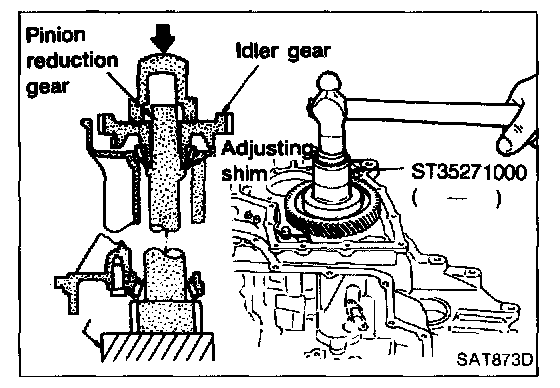
3. Install reduction gear and reduction gear bearing adjusting shim selected in step 2-e on transmission case.
4. Press idler gear bearing inner race on idler gear.
5. Press idler gear on reduction gear.
- Press idler gear so that idler gear can be locked by parking pawl.
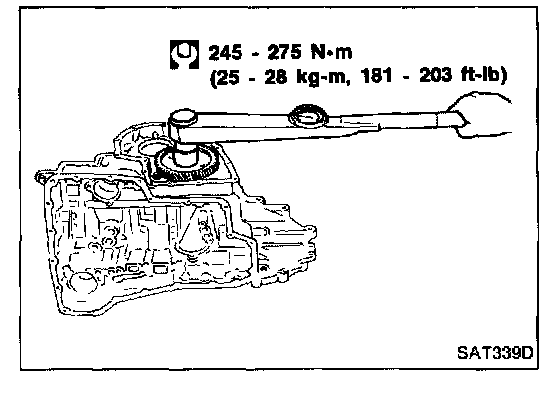
6. Tighten idler gear lock nut to the specified torque.
- Lock idler gear with parking pawl when tightening lock nut.
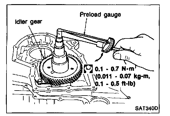
7. Measure turning torque of reduction gear.
- When measuring turning torque, turn reduction gear in both directions several times to seat bearing rollers correctly.
Turning torque of reduction gear: 0.11 - 0.69 N.m (1.1 - 7.0 kg-cm, 0.95 - 6.08 in-lb)
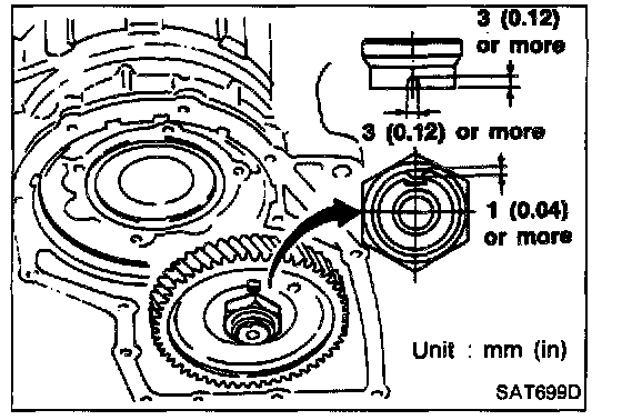
8. After properly adjusting turning torque, clinch idler gear lock nut as shown (only RL4F03V).
OUTPUT SHAFT BEARING PRELOAD - RL4F03A
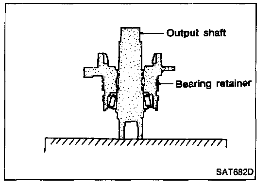
1. Select proper thickness of output shaft bearing adjusting spacer using the following procedures.
a. Remove paper rolled around output shaft.
b. Place bearing retainer on output shaft.
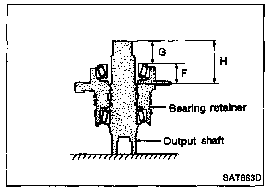
c. Place output gear bearing inner race on bearing retainer.
d. Measure dimensions "G" and "H" and calculate dimension "F".
- "F": Distance between the surface of output gear bearing inner race and adjusting shim mating surface of output shaft.
F = H - G
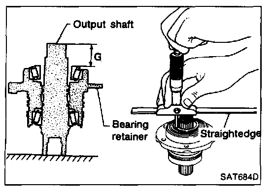
- Measure dimension "G" between end of output shaft and surface of output gear bearing inner race.
- Measure in at least two places.
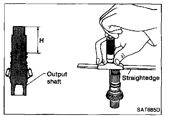
- Measure dimension "H" between end of output shaft and adjusting spacer mating surface of output shaft.
- Measure in at least two places.
- Calculate dimension "F".
F = H - G
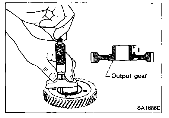
e. Measure distance "I" between end of output gear (adjusting spacer mating surface) and bearing inner race fitting surface.
f. Calculate dimension "T(2)".
- "T(2)": Distance between adjusting spacer mating surface of output gear and output shaft
T(2) = F - I
g. Select proper thickness of output shaft bearing adjusting spacer using Specifications table as a guide.
Output shaft bearing adjusting spacer: Refer to Specifications.
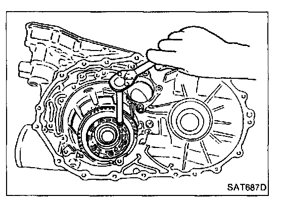
2. Install bearing retainer on transmission case.
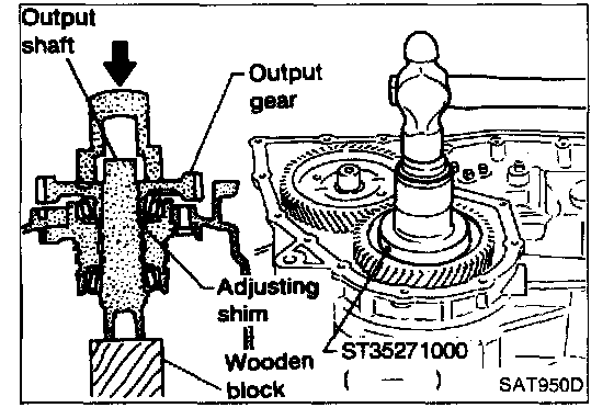
3. Place output shaft on bearing retainer.
4. Place output shaft bearing adjusting spacer selected in step 1-g on output shaft.
5. Press output gear bearing inner race on output gear.
6. Press output gear on output shaft.
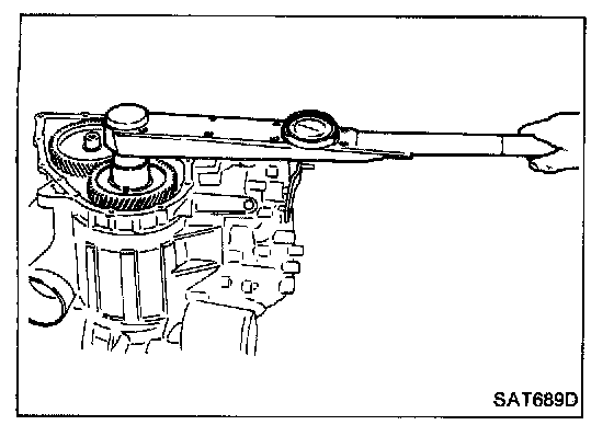
7. Tighten output gear lock nut to specified torque.
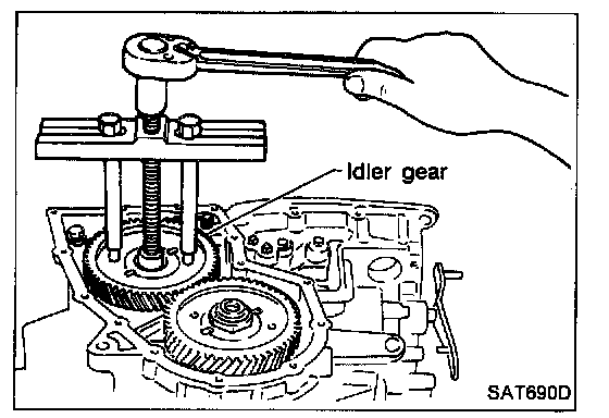
8. Remove idler gear to measure output shaft preload.
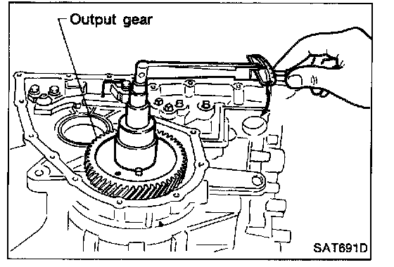
9. Measure turning torque of output shaft.
- When measuring turning torque, turn output shaft in both directions several times to seat bearing rollers correctly.
Turning torque of output shaft: 0.25 - 0.88 N.m (2.5 - 9.0 kg-cm, 2.2 - 7.8 in-lb)
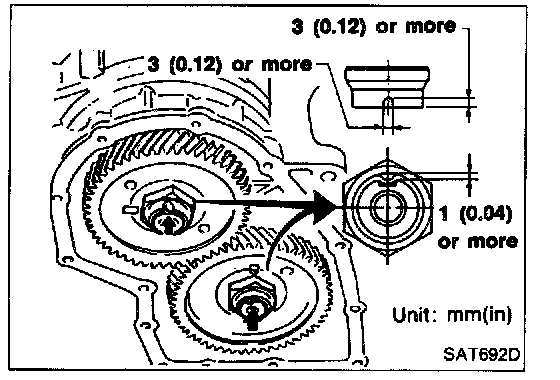
10. Install idler gear and tighten lock nut to specified torque.
11. After properly adjusting "turning" torque, clinch idler gear and output gear lock nuts as shown.
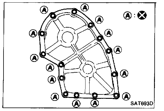
12. Install new gasket and side cover on transmission case.
OUTPUT SHAFT END PLAY - RL4F03V
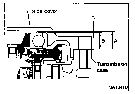
- Measure clearance between side cover and the end of the output shaft bearing.
- Select proper thickness of adjusting shim so that clearance is within specifications.
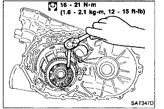
1. Install bearing retainer for output shaft.
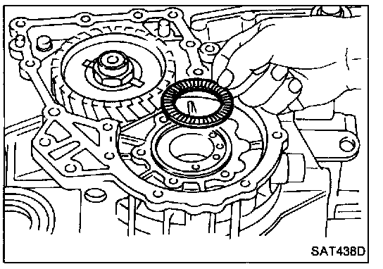
2. Install output shaft thrust needle bearing on bearing retainer.
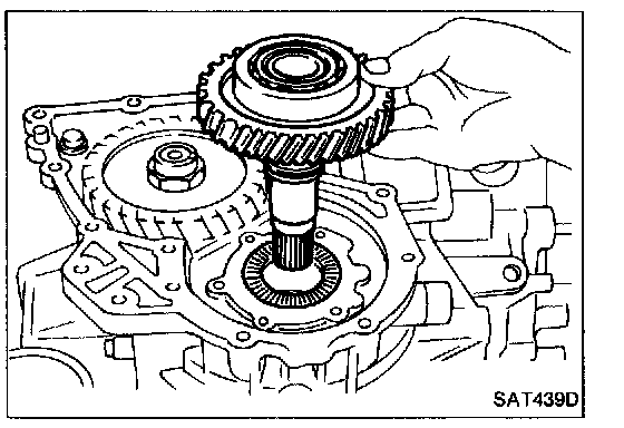
3. Install output shaft on transmission case.
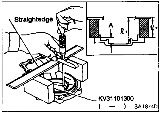
4. Measure dimensions "l(1)" and "l(2)" at side cover and then calculate dimension "A".
- Measure dimension "l(1)" and "l(2)" in at least two places.
"A": Distance between transmission case fitting surface and adjusting shim mating surface.
A = l(1) - l(2) l(2): Height of gauge
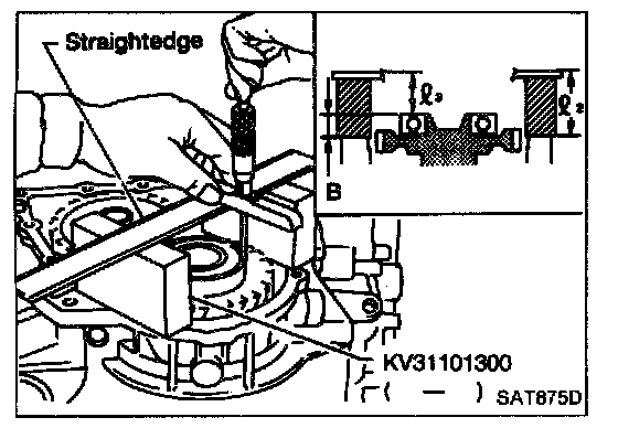
5. Measure dimensions "l(2)" and "l(3)" and then calculate dimension "B".
- Measure "l(2)" and "l(3)" in at least two places.
"B": Distance between the end of output shaft bearing outer race and the side cover fitting surface of transmission case.
B = l(2) - l(3) l(2): Height of gauge