Antitheft - Vehicle Security System Installation
91nissan02
Classification: EL91-003
Section: Electrical
Reference: TECHNICAL BULLETIN NTB91-012
Model: 1991 NX Coupe
Date: February 7, 1991
1991 NX COUPE VSS INSTALLATION INSTRUCTIONS
APPLIED MODEL: 1991 NX Coupe (B13)
SERVICE INFORMATION
The following pages of this Technical Bulletin contain installation instructions for the Nissan Vehicle Security System Kit available for the 1991 NX Coupe.
Please make sure that the appropriate dealership technicians become familiar with these instructions to assure high quality installations.
1991 NX COUPE
VSS INSTALLATION INSTRUCTIONS
NOTE: THE FOLLOWING KIT AND PARTS ARE REQUIRED FOR THE INSTALLATION
OF THIS VSS KIT:
Auxiliary Horn Relay Kit (Part No. 999M2-H1000)
M10 x 1.5 nut (for pinswitch installation)
M10 or equivalent tooth washer
BEFORE STARTING, DISCONNECT THE BATTERY NEGATIVE CABLE
Figure 1:
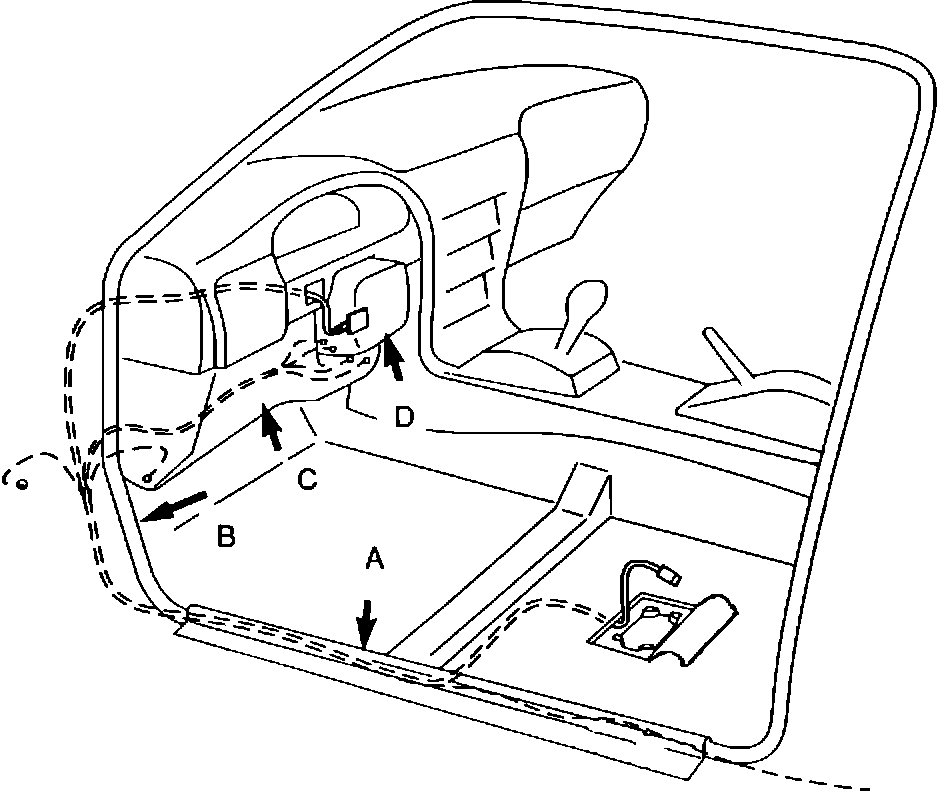
A. INTERIOR
1. Remove the driver's seat mounting bolts. Disconnect the seat belt switch connector and carefully remove seat.
2. Remove the following trim panels:
- Left door sill protector (A) and wire harness protector
- Left kick panel(B)
- Undercolumn finisher and the steel panel behind the finisher (C)
- Steering column finisher (D)
Figure 2:
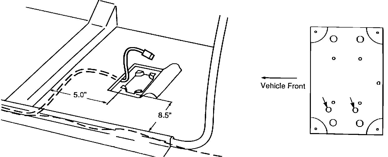
3. Place the module mounting plate on the carpet under the driver's seat at the location shown. Using the plate as a template, cut a three sided flap in the carpet and padding. Remove the padding only. Place the plate on the floor and mark the location of the holes as shown. Drill two 3/16" holes, remove any burrs and apply NISSAN RUST PREVENTATIVE (999MP-A6000). Apply the double sided tape to the bottom of the plate. Do not touch the adheasive surface. Fasten the plate to the floor with the sheet metal screws. Attach the electronic module to the mounting plate with the four black screws. DO NOT OVERTIGHTEN OR STRIP THE THREADS.
Figure 1:
B. WIRE HARNESS ROUTING AND CONNECTIONS
CAUTION: THE GREEN AND YELLOW VEHICLE WIRE HARNESSES CONTAIN WIRES FOR THE AIRBAG SYSTEM. DO NOT CUT THESE HARNESSES.
1. Lay out the VSS wiring harness. Remove any tangles and separate one of the single BLACK wires. Plug the large connector into the electronic module and lay the harness as shown in Figure 1. Route all but the single BLACK wire under the carpet, along the underseat crossmember, along the door sill, under the plastic harness protectors, and up to the kick panel area.
2. Remove the switch blank, located left of the steering column, by pushing out from behind (see Figure 1). Route the small connector harness up through the hole and attach to the status monitor. Snap the monitor into place. Apply the status monitor overlay (if necessary) by CAREFULLY aligning it and smoothing from the center out.
Figure 4:
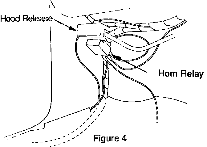
3. Mount the Horn Relay to the vehicle just below the hood release. Remove the screw that holds the hood release and attach the Horn Relay with the wires toward the front of the car.
4. Connect the two and four wire branches as follows:
GRAY ... Locate the RED/WHITE wire in the sill wire harness. Connect with RED Scotchlok.
Figure 3:
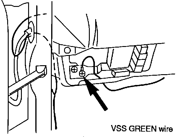
GREEN ... Ground the ring terminal with the mounting screw located left of the fuse block.
See Figure 3.
Route the remaining wires (except the BLACK hoodswitch wire) to the undercolumn area.
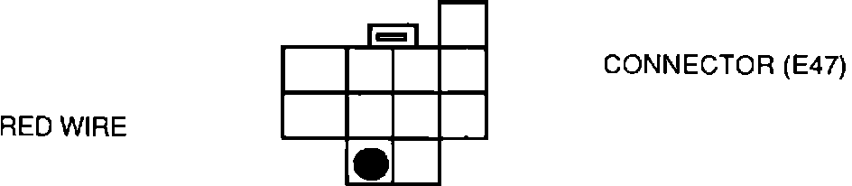
RED ... 1. Locate the RED wire on the 11-pin connector (E47) at the base of the
combination lighting switch and connect it to the RED VSS wire with a BLUE Scotchlok.
2. Connect the RED Horn Relay wire to the RED VSS wire with a BLUE ScotchLok.
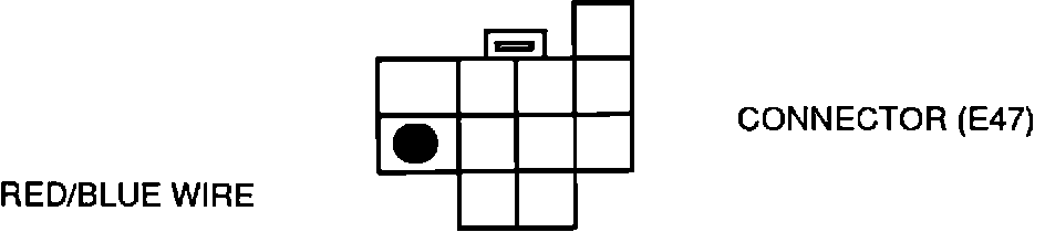
YELLOW ... On the same 11-pin connector (E47), connect to the RED/BLUE clearance light
wire with a BLUE Scotchlok.

ORANGE ... Locate the 8-pin connector (E49) for the wiper controls. Connect to the PINK
wire with a RED Scotchlok.
DARK GREEN/BLACK ... Attach to the GREEN/BLACK Horn Relay wire with a WHITE
ScotchLok. Cut the wires to length before attaching the ScotchLok to avoid bundles of wire.
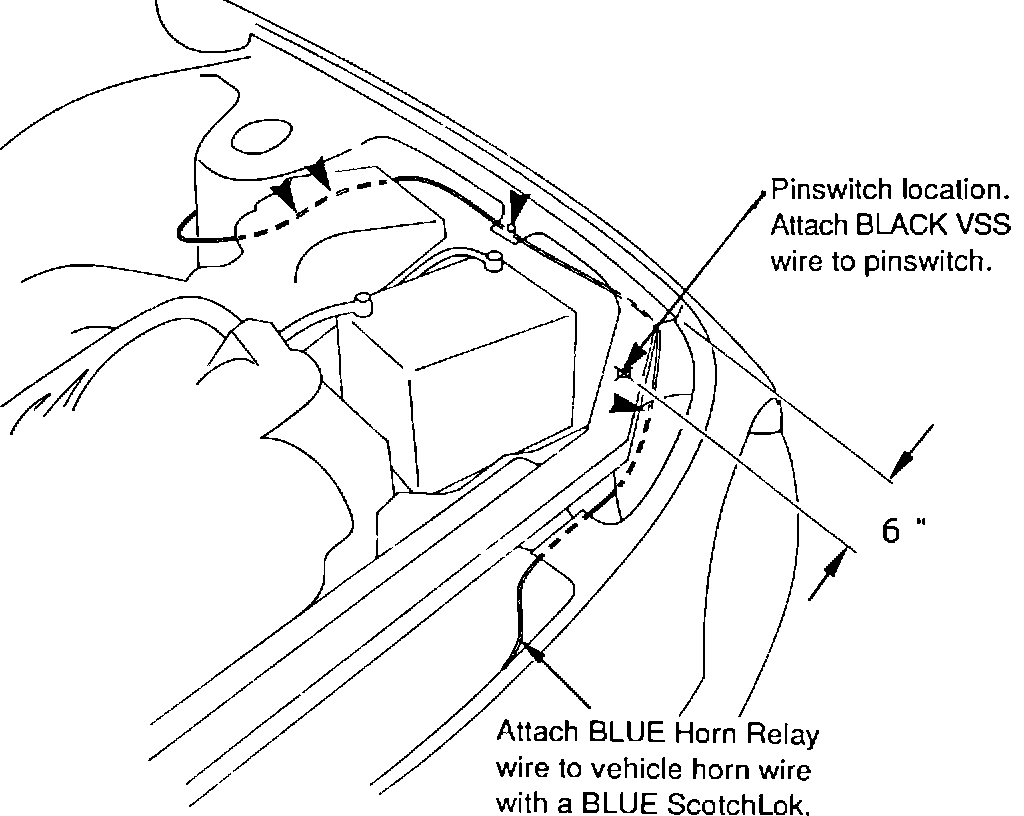
Figure 3:
4. Route the BLACK hood switch wire and the BLUE Horn Relay wire as follows:
A. Remove the left front wheelhouse liner.
B. Locate and remove the unused grommet located in front of the left door harness. Refer to Figure 3. Cut a small hole in the grommet.
C. Route the wires through the grommet hole and through the grommet. Pass the wires up to and through the 3/4" hole located to the rear of the left strut tower (see Figure 5). Route the wires around the strut tower and up to the radiator.
D. Install the pinswitch in the hole on the radiator core support, 6" from the left fender, using the M10 nut and the tooth washer on the bottom side. Check to see if the pin moves down at least 1/8" when the hood is closed. Use the washers in the kit, if the pin needs to be raised.
E. Attach the BLACK wire to the pinswitch. Draw the excess BLACK wire back into the kick panel area and tape up the bundle.
F. Route the BLUE Horn Relay wire to the horn, cut off excess wire, and attach to the horn with a RED ScotchLok. Wrap the connection with electrical tape.
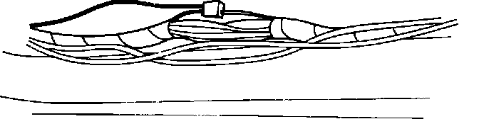
G. Fasten these wires to the vehicles wire harnesses and to the vehicle with the tie wraps, as indicated in Figure 5. Reset the grommet and seal with RTV silicon sealer. Install wheelhouse liner. Wrap the wires with electrical tape where they contact a sharp edge, especially near the body panel access holes.
Figure 6:
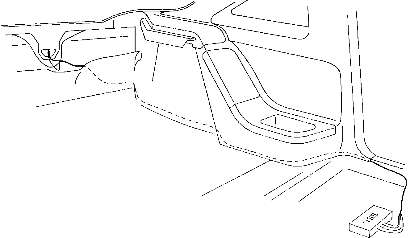
5. Route and attach the BLACK trunk wire as follows: (See Figure 6)
A. Remove the rear seat bottom by pulling the release tabs located under the cushion about 6" from the sides.
B. Loosen the bottom of the quarter panel finisher.
C. Route the wire: (1) inside the wire harness protector located under the sill panel, (2) under and behind the quarter panel finisher, (3) under the rear seat back hinge, and (4) behind the rear compartment finishers up to the taillight area.
D. Remove the trim piece located at the top edge of hatch opening.
E. Route the BLACK wire behind the taillight panel and up to the hatch release mechanism.
F. Cut off the bullet end and attach this wire to the RED wire at the release mechanism with a RED ScotchLok.
G. Install all panels and rear seat.
C. CHECK OUT THE INSTALLATION AS SHOWN IN THE INSTALLATION CHECK OUT SECTION.
D. INSTALL ALL TRIM AND FRONT SEAT.
Front seat torque specifications: 18-23 ft.lbs. (25-31 N-m, 2.5-3.2 Kg-m).