Disassembly and Assembly
Fig. 23 Exploded View Of Oil Pump Assembly:
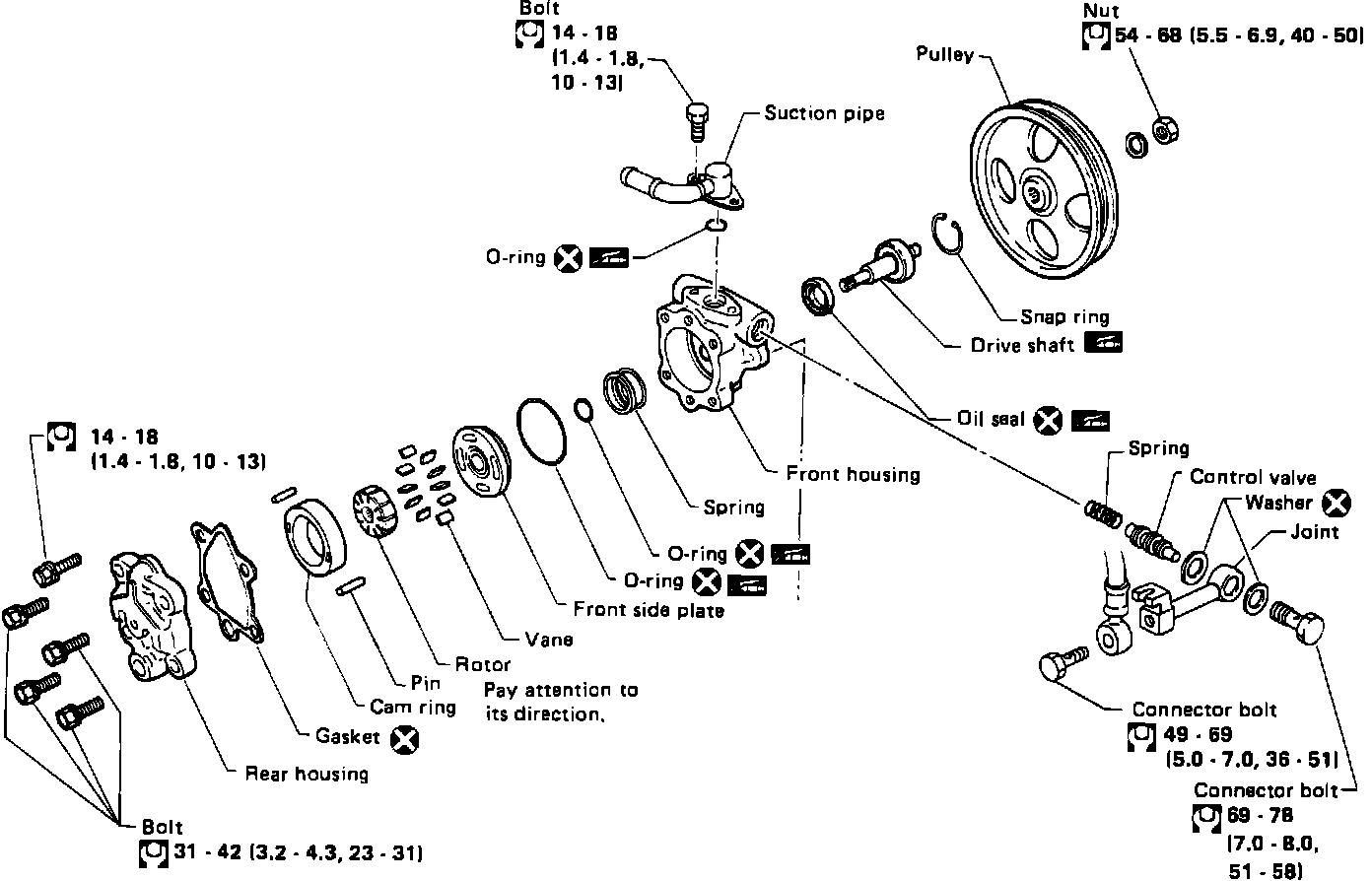
When performing this procedure ensure work area is clean. Do not use rags when cleaning parts, use nylon cloths or paper towels. Do not let foreign matter enter or contact parts.
1. Remove snap ring, then draw driveshaft out of pump, Fig. 23.
2. Using a screwdriver, remove oil seal.
3. Remove connector, then the control valve from front housing. Do not drop control valve.
4. Disassemble remaining parts as shown in Fig. 23.
Fig. 24 Rotor Installation:
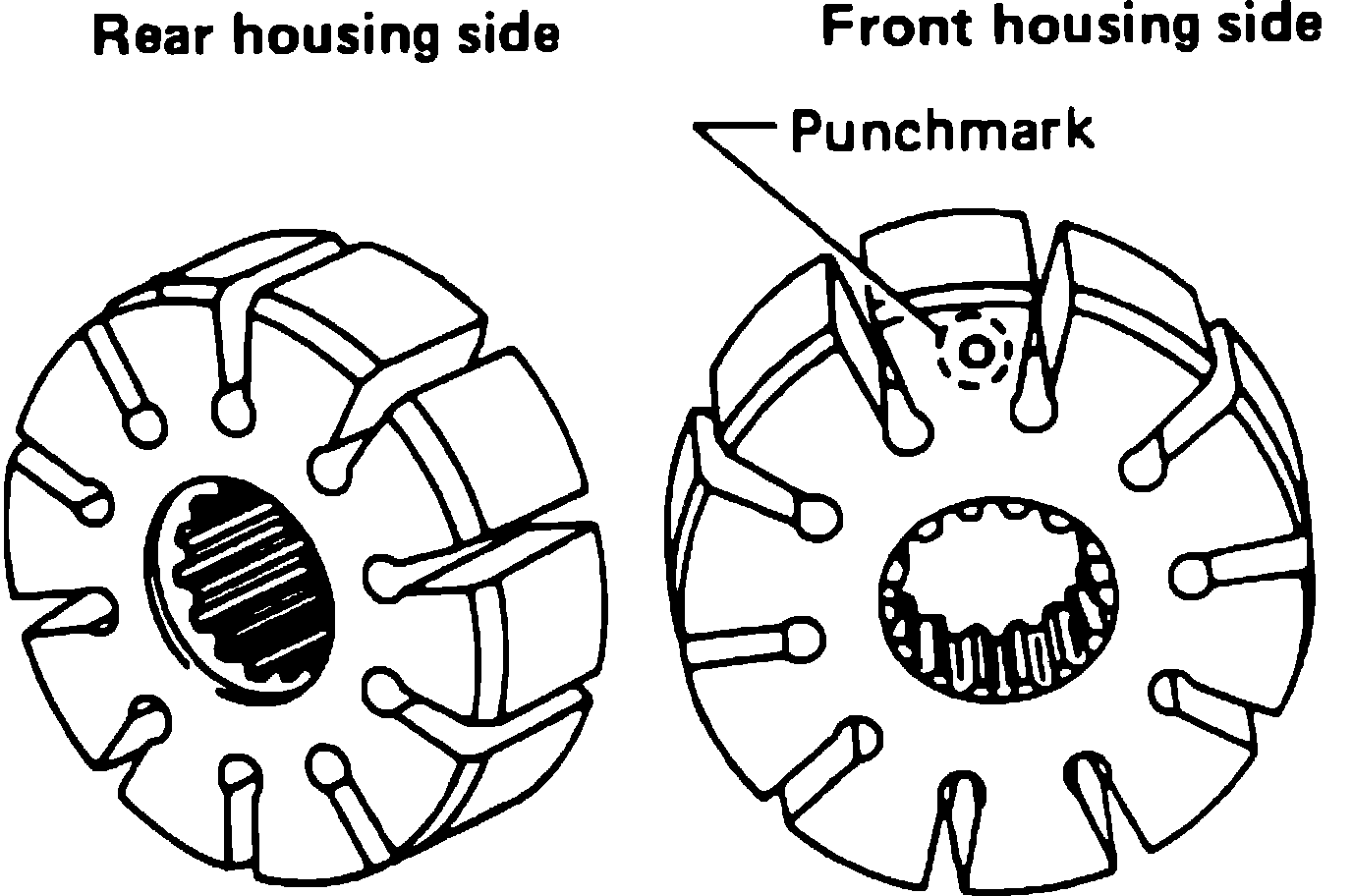
Fig. 25 Installing Vanes Into Rotor:
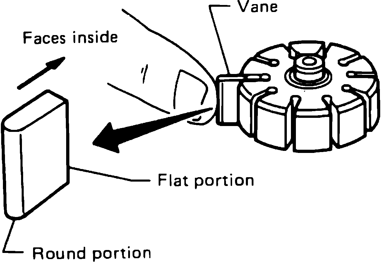
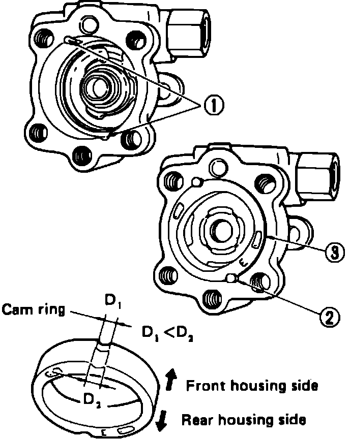
Fig. 26 Installing Cam Ring & Rotor Into Front Housing:
5. Reverse procedure to assemble, noting the following:
a. Use new seals and O-rings, ensure they are installed properly and in the correct direction.
b. Cam ring, rotor and vanes must be replaced as a set.
c. Coat all parts with automatic transmission fluid prior to assembly.
d. When installing rotor, refer to Fig. 24, for correct direction.
e. When inserting vanes into rotor, rounded surfaces of the vanes must be facing the cam ring side as shown in Fig. 25.
f. On electronically controlled pumps, a wave washer is installed instead of the spring.
g. On all pumps, insert pin into groove of front housing, then install the rotor and cam ring as shown in Fig. 26.