How to Install A Nissan 240SX Air Conditioner
FIGURE 1:
For A/C Systems B7000-40F00 and B7000-43F00
Installation Instruction Manual Supplement
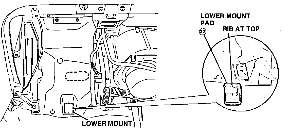
1. Installation hint: Early production vehicles (7/88 and 8/88 only) may have insulating material that does not properly align with the hole location for the evaporator lower mount. (Refer to Figure 1).
Be sure to avoid catching the edge of the insulating material under the lower mount pad during installation. If necessary, trim a small portion of the insulator to permit proper installation of the lower mount pad.
FIGURE 2:
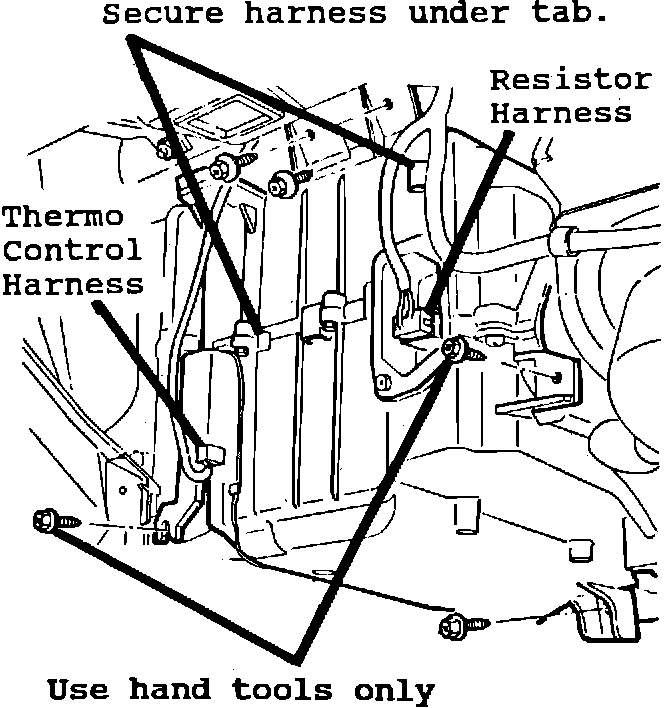
FIGURE 3:
2. Installation procedure: Using the following procedure, install the evaporator assembly and drain hose. (Refer to Figures 2 and 3).
A. Loosen but DO NOT REMOVE the blind caps on the evaporator tubes.
B. Place the evaporator assembly in mounting position, then proceed as follows:
1. Loosely install the two side mounting screws.
2. Loosely install the top and bottom mounting bolts.
3. Using hand tools only, secure side mounting screws.
4. Secure top and bottom mounting bolts.
C. Connect and secure (under tabs) the following wire harnesses:
1. to thermo control
2. to resistor
D. (Continued on Page 2)
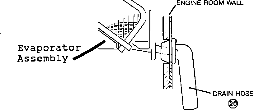
D. From the engine room, install the drain hose to the engine room wall as shown below in Figure 3. Insure that the end of the drain hose is pointing straight down.
NOTE: As a final check, insure that the drain hose is properly seated into the engine room wall, and the case drain pipe is properly positioned in the drain hose.
FIGURE 4:
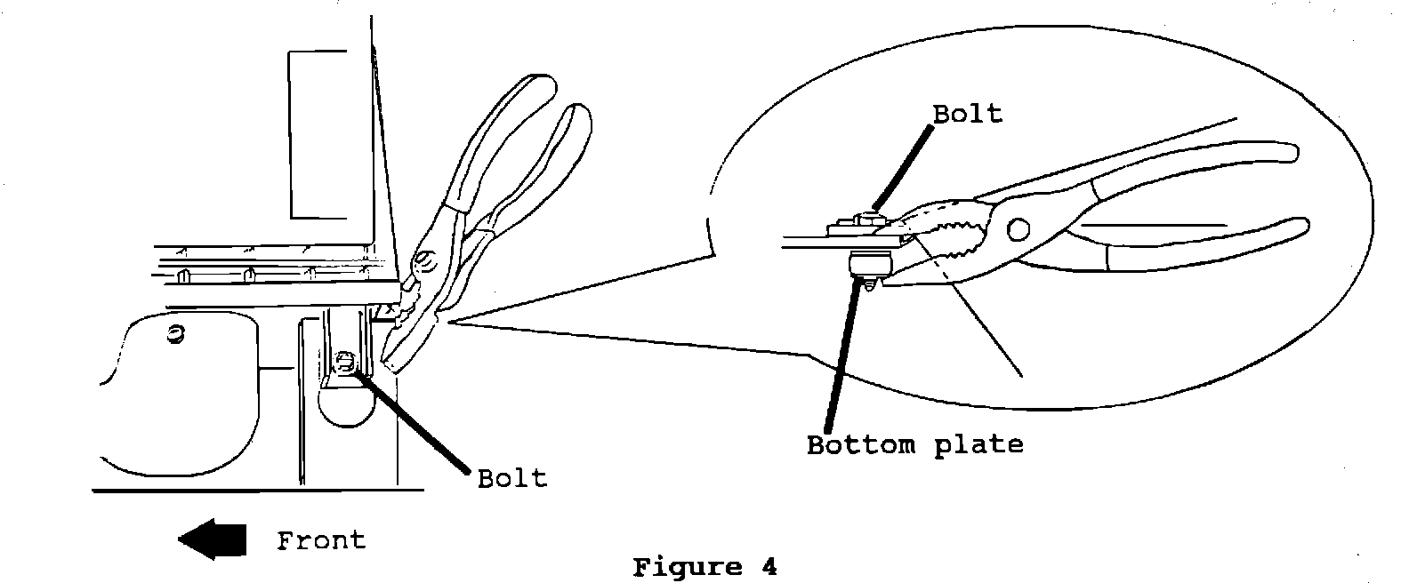
3. Installation procedure: Before turning the bolt, when removing (and reassembling) - the air filter assembly as instructed in step 18B in the installation manual use a pair of pliers to prevent the bottom plate of the mount from turning as illustrated below in Figure 4.
4. Installation procedure: Shroud removal can be obtained easily (without causing damage to the radiator fins) if ALL of the following conditions exist.
A. the right side (passenger side) top radiator mount is removed, and the left side (driver's side) top radiator mount is installed, so that the radiator is held securely
B. the shroud bottom and side pieces are removed
C. by lifting the driver's side of the shroud first, and twisting the shroud toward rear of vehicle while removing
FIGURE 5:
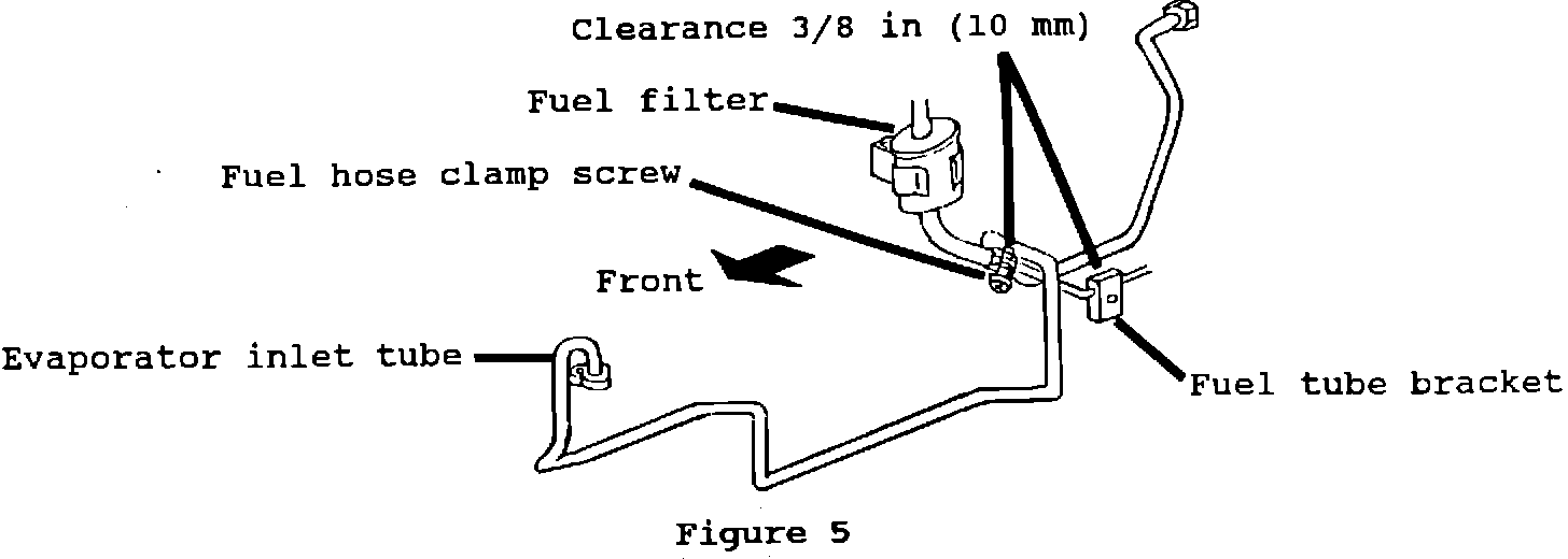
5. Installation procedure: For proper installation of the evaporator inlet tube, refer to steps 36A thru E and Figures 27, 28, and 29 on Pages 7 and 8 in the installation manual.
After installing the evaporator inlet tube, it is very important to confirm that adequate clearance [3/8 in (10 mm)] exists between the evaporator inlet tube and all vehicle parts, especially: a) the evaporator inlet tube and the fuel hose clamp screw, and b) the evaporator inlet tube and the fuel tube bracket. (Refer to Figure 5).
If the evaporator inlet tube is left in contact with vehicle parts, A/C tube failure may result.
FIGURE 6:
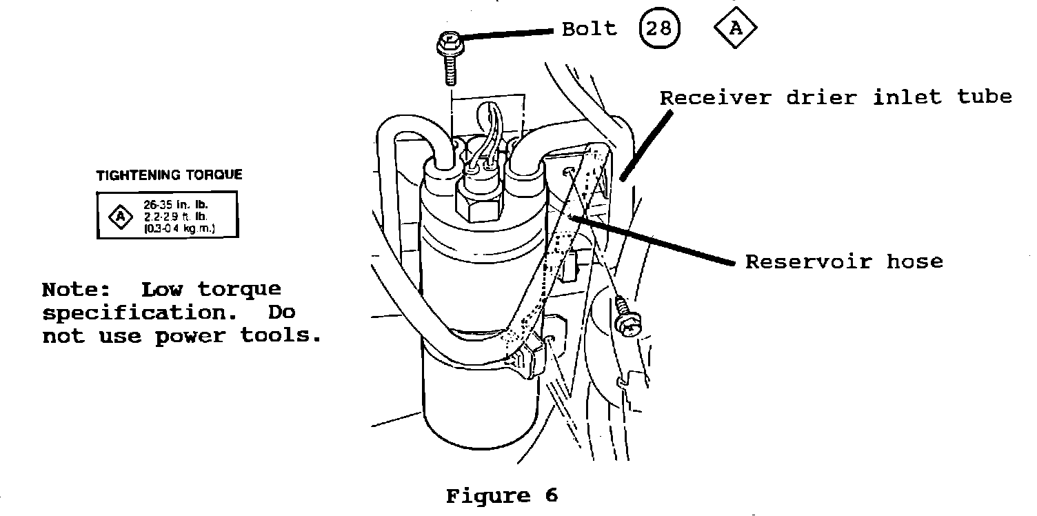
6. Installation procedure: While mounting the receiver drier assembly to the battery tray and right inner fender, insure that the reservoir hose is between the receiver drier assembly and the receiver drier inlet tube (the larger diameter tube) as shown below in Figure 6.
A low torque specification is required to secure the receiver drier inlet and outlet tubes. Therefore, do not use power tools for these connections.
FIGURE 7:
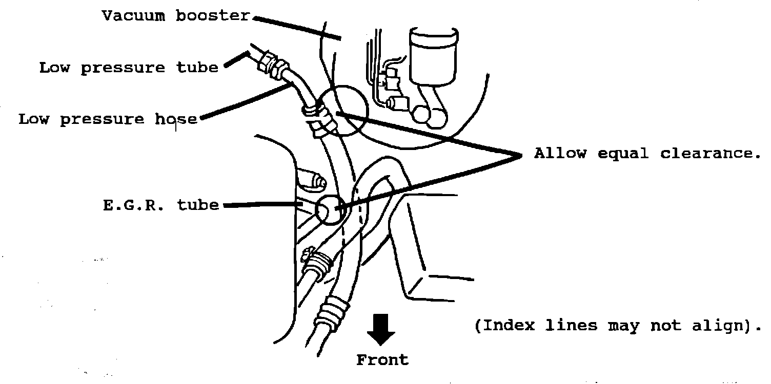
7. Installation procedure: Before connecting the evaporator end of the low pressure tube, position the other end of the tube above the
E.G.R. tube. ..... After connecting the low pressure tube to the low
pressure hose (Refer to Figure 7), adjust the position of the low hose so that equal clearance exists between: a) the low hose and the vacuum booster, and b) the low hose and the E.G.R. tube. (The index lines may not align). Torque the fitting to specification.
8. Installation hint: The A/C switch indicator light will not illuminate until the system has been charged (pressure switch closed).