Engine Assembly
CYLINDER HEAD
1. Install valve component parts, noting the following:
a. Always use new valve oil seals.
b. Before installing valve oil seal, install inner valve spring seat.
c. Install outer valve spring with its narrow pitch side toward cylinder head side.
2. Install camshaft.
3. Install camshaft locate plate, torquing attaching bolt to 58-65 ft. lbs.
4. Apply engine oil to new camshaft oil seal and install it in place.
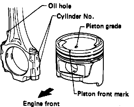
Fig. 19 Piston & connecting rod identifying marks:
PISTON & ROD ASSEMBLY
1. Numbers are stamped on connecting rod and cap corresponding to each piston, Fig. 19. Do not intermix parts.
2. When pressing piston pin into connecting rod, apply engine oil to pin and small end of connecting rod.
3. After assembling, ensure piston swings freely.
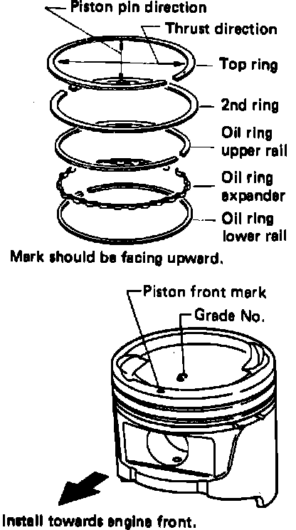
Fig. 20 Piston ring installation position:
ENGINE ASSEMBLY
1. Install piston assembly, setting piston rings as shown, Fig. 20.
Fig. 21 Main bearings:
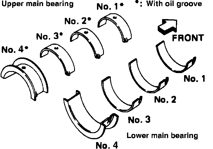
2. Set main bearings in proper position on cylinder block, Fig. 21. If cylinder block, crankshaft or main bearing is reused, main bearing clearance must be measured. Upper bearings have oil groove.
3. If crankshaft, cylinder block and main bearing are replaced, thickness of main bearings must be selected as follows:
a. Grade No. of each cylinder block main journal is punched on respective cylinder block.
b. Grade No. of each crankshaft main journal is punched on respective crankshaft.
c. Select main bearing whose thickness grade is equal to sum of thickness grades of crankshaft journal and main journal.
4. Apply engine oil to main bearing surfaces on both sides of cylinder block and cap.
Fig. 22 Main bearing cap bolt tightening sequence:
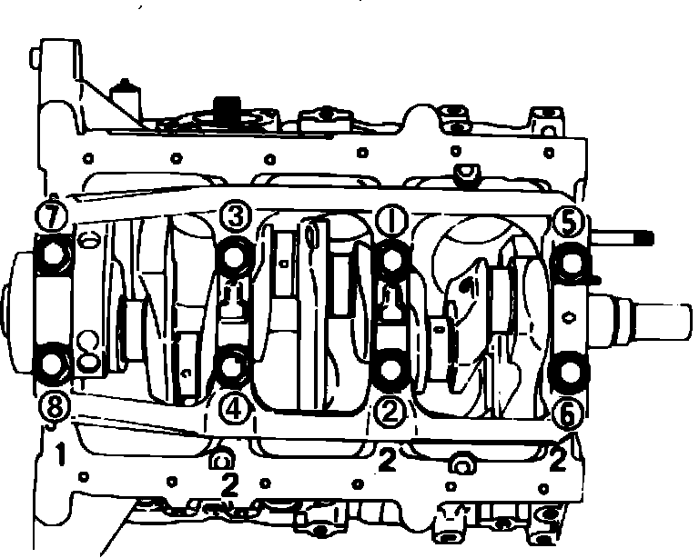
5. Install crankshaft and main bearing caps, retorquing bolts to 67-74 ft. lbs. in two or three stages in sequence, Fig. 22.
6. Ensure crankshaft turns smoothly by hand.
7. Measure crankshaft free endplay at No. 4 bearing. Clearance should be .0020-.0067 inch. If clearance exceeds .0118 inch, replace No. 4 main bearing.
8. Measure connecting rod side clearance. Clearance should be .0079-.0138 inch. If clearance exceeds .0157 inch, replace connecting rod and/or crankshaft.
9. Install pistons with connecting rods in proper cylinders, noting the following:
a. Be careful not to scratch cylinder wall with connecting rod.
b. Apply engine oil to cylinder wall, piston and bearing.
c. Arrange so that front mark on piston head faces toward front of engine.
10. Install connecting rod bearing caps, torquing to 33-40 ft. lbs.