Cylinder Head Assembly: Service and Repair
REMOVAL1. Disconnect battery ground cable.
2. Remove timing belt as previously described.
Fig. 7 Intake manifold bolt loosening sequence:
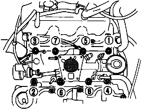
3. Remove air cleaner and the intake manifold with injection body, loosening intake manifold attaching bolts in sequence, Fig. 7.
4. Remove power steering pump bracket.
5. Remove camshaft pulleys and the rear timing cover attaching bolts.
6. Remove compressor and rocker covers.
Fig. 9 Cylinder head bolt loosening sequence. 1988:
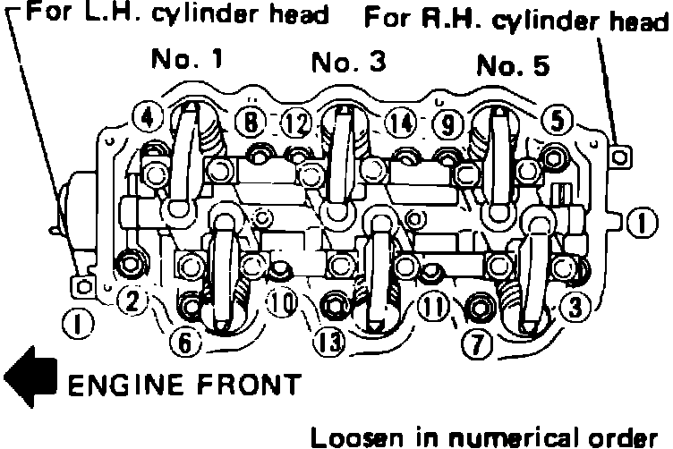
7. Remove cylinder head with exhaust manifold, loosening attaching bolts in sequence, Fig. 9.
INSTALLATION
1. Install cylinder head with new gasket.
Fig. 10 Cylinder head bolt tightening sequence:
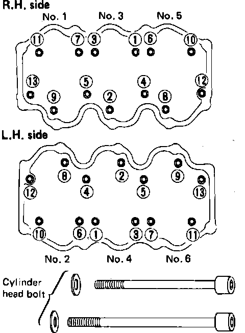
2. Apply oil to threaded portion and seat surface of bolts and tighten cylinder head bolts with washers, in sequence, Fig. 10 as follows. Bolt Nos. 4, 5, 12 and 13 are 127 mm long and all others are 106 mm long.
a. Torque all bolts to 22 ft. lbs.
b. Torque all bolts to 43 ft. lbs.
c. Loosen all bolts completely.
d. Torque all bolts to 22 ft. lbs.
e. Torque all bolts to 40-47 ft. lbs. or, if angle wrench is available, turn all bolts 60-65° clockwise.
3. Install rear belt cover.
Fig. 9 Camshaft Pulley Identification:
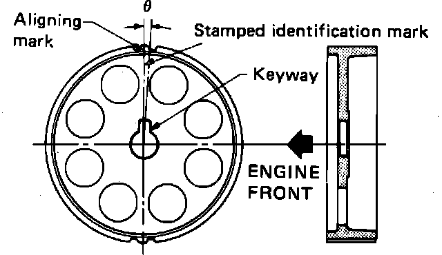
4. Install camshaft, locate plate, rear cover and camshaft pulley. Torque camshaft pulley attaching bolt to 58-65 ft. lbs. while counterholding pulley and torque locate plate bolt to 58-65 ft. lbs., Do not intermix camshaft pulleys. Right hand pulley has R3 stamped on it and the aligning mark is 53 minutes off center, Fig. 11, while left hand pulley has L3 stamped on it and the aligning mark is -3° 27 minutes off center.
5. Ensure No. 1 cylinder is set at TDC on its compression stroke. Crankshaft timing pulley mark should be aligned with mark on oil pump housing and camshaft pulley mark should be aligned with mark on left cover.
6. Install timing belt and adjust belt tension, then install front upper and lower belt covers. Refer to ``Timing Belt, Replace.''
7. Install valve lifters and lifter guide. Assemble valve lifters to their original positions and secure with wire.
8. Install rocker shafts with rocker arms and tighten rocker shaft attaching bolts. Torque bolts to 13-16 ft. lbs. gradually in two or three stages, working outward from center position.
9. Install rocker cover, ensuring rocker cover bolts, washers and trays are free from oil.
Fig. 12 Intake nut & bolt tightening sequence:
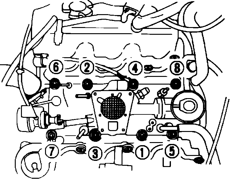
10. Install intake manifold, tightening attaching nuts and bolts in sequence, Fig. 12, as follows:
a. Torque nuts to 2.2-3.6 ft. lbs.
b. Torque nuts to 17-20 ft. lbs.
c. Torque bolts to 2.2-3.6 ft. lbs.
d. Torque bolts to 12-14 ft. lbs.
Fig. 11 Exhaust Manifold Bolt Tightening Sequence:
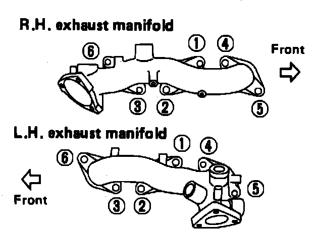
11. Install exhaust manifolds and connecting tube, torquing attaching bolts in sequence, Fig. 13, to 13-16 ft. lbs.
Fig. 14 Setting distributor gear position:
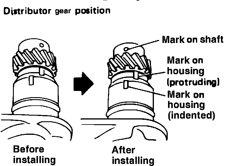
12. Set distributor gear position, Fig. 14, ensuring No. 1 piston is at TDC on its compression stroke.
13. Install distributor to cylinder head.