Brake Pedal Assy: Adjustments
Brake Pedal Adjustment:
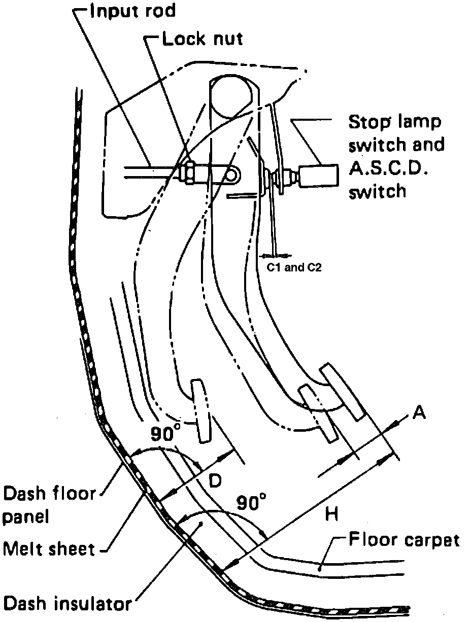
Check brake pedal free height from melt sheet. Adjust if necessary.
H: Free height
Refer to image.
D: Depressed height
Refer to image.
Under force of 490 N (50 kg, 110 lb) with engine running.
C1: Clearance between pedal stopper and threaded end of stop lamp switch
0.3 - 1.0 mm (0.012 - 0.039 in)
C2: Clearance between pedal stopper and threaded end of A.S.C.D. switch.
0.3 - 1.0 mm (0.012-0.039 in)
A: Pedal free play
1 - 3 mm (0.04 - 0.12 in)
1. Adjust pedal free height with brake booster input rod. Then tighten lock nut.
Fig. 8 Adjusting Input Rod:
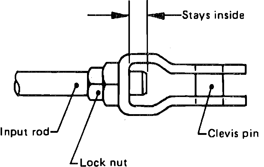
NOTE: Make sure that the tip of input rod stays inside.
2. Adjust clearance "C1" and "C2" with stop lamp switch and A.S.C.D. switch respectively. Then tighten lock nuts.
3. Check pedal free play.
NOTE: Make sure that stop lamp is off when pedal is released.
4. Check brake pedal depressed height with engine running. If depressed height is below the specified value, check brake system for leaks, accumulation of air or any damage regarding component parts (master cylinder, wheel cylinder, etc.), and make the necessary repairs.