Torsion Bar - Installation Caution
Reference: Date:TECHNICAL BULLETIN TS86-052 May 5, 1986
Classification: Models:
TM86-009 Section: Transmission 1986.5 4WD Truck
SPECIAL TRANSMISSION SERVICE
INSTALLATION CAUTION, 1986.5 4WD TRUCK
This bulletin supplements Technical Bulletin TM86-003 (TS86-022). DO NOT discard the original bulletin.
TORSION BAR:
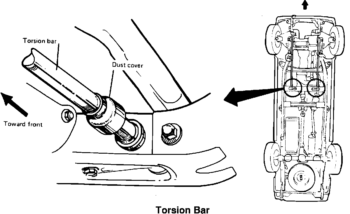
SERVICE CAUTION
When installing the torsion bar springs in a 4WD truck (page 4/18, step 12 in original bulletin) make sure the torsion bar is fully seated in the rear anchor arm as follows:
1. Pull back the dust cover at the rear of the torsion bar.
2. Insert the torsion bar into the rear anchor arm until it contacts the stop.
TORSION BAR REAR SPLINE AREA:
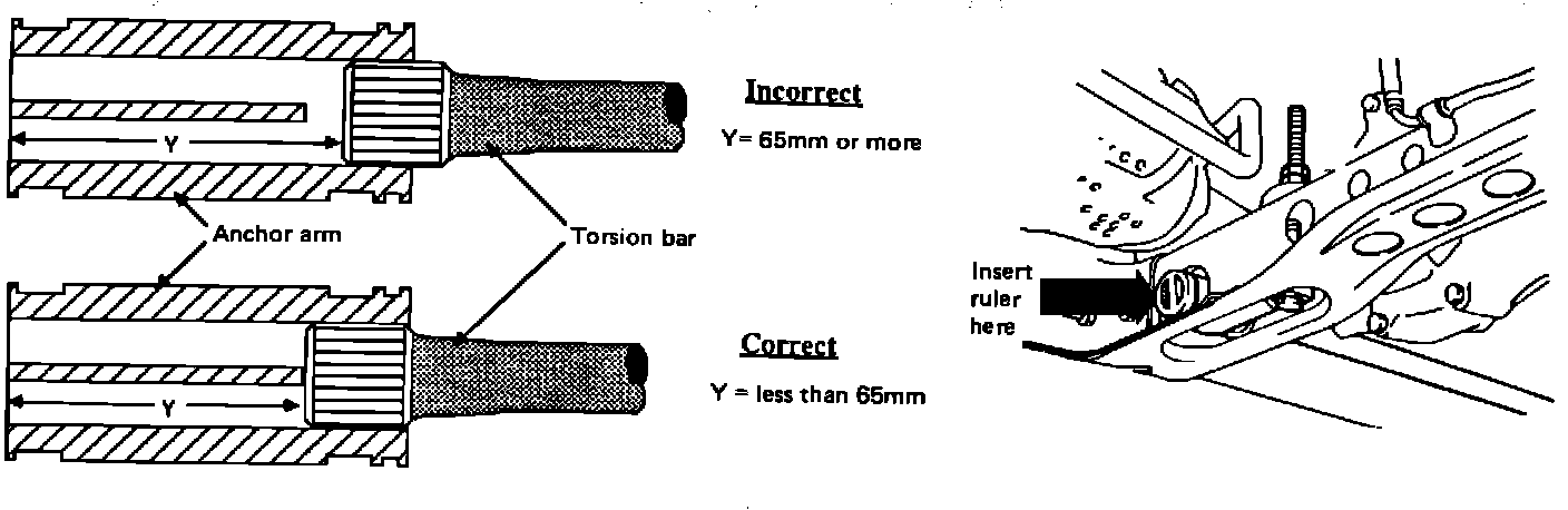
3. Then measure distance "Y" as shown below. Distance "Y" should be less than 65 mm.
SLIDE TORQUE ARM:
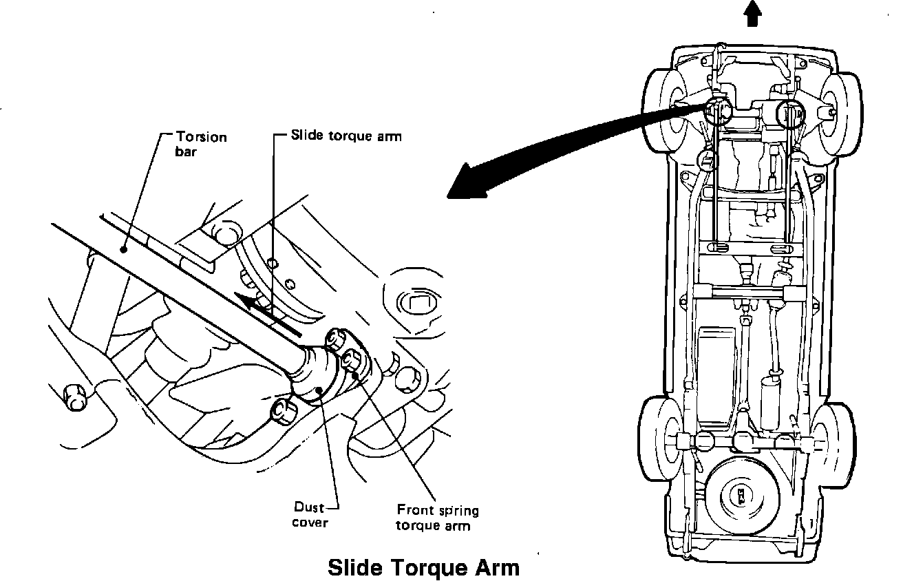
4. Reposition the dust cover on the rear anchor arm.
5. Slide the front spring torque arm back to expose the torsion bar splines.
TORSION BAR AND LOWER LINK SPINDLE:
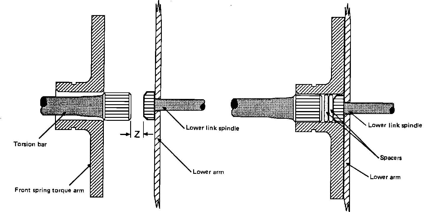
6. Add spacers (suitable washers) to fill the gap (distance Z) between the torsion bar and lower link spindle. Apply grease to prevent the spacers from rattling.
TORQUE ARM AND DUST COVER:
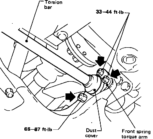
Torsion Bar Front Spline Area
7. Reinstall the torque arm and dust cover (Fixing bolt tightening torque: 14 mm nuts = 33-44 ft.lbs., 19 mm nut = 66-87 ft.lbs.).