M/T - Shift Fork Installation Cautions
Reference: Date:TECHNICAL BULLETIN TS86-039 March 21, 1986
Classification: Section: Models:
TM86-005 Transmission 1986.5 Truck
SPECIAL TRANSMISSION SERVICE CAUTIONS, 1986.5 TRUCK
This bulletin supplements Technical Bulletins TM86-002 and TM86-003. DO NOT discard the original bulletins.
SERVICE INFORMATION
This bulletin contains more detail and additional cautions of the shift fork replacement procedures in Technical Bulletins TM86-002 and TM86-003. The procedures in this bulletin when replacing the 1st/2nd and reverse shift forks. Use the procedure in the original bulletins to remove and replace the transmission.
SHIFT FORK REPLACEMENT PROCEDURES
NOTE: Items that are double underlined are revisions or additions to the original procedure.
INTERLOCK STOPPER:
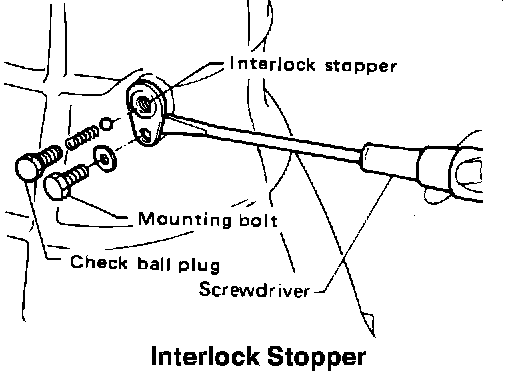
1. Remove the check ball plug (14 mm), check spring and check ball. Then remove the 14 mm mounting bolt and interlock stopper from the transmission case (not in rear extension). Save the check ball plug and discard the mounting bolt.
CAUTION: If the interlock stopper is not removed, the striking interlock will be damaged during case removal.
2. Remove the clutch release lever from the transmission case.
RETURN SPRING:
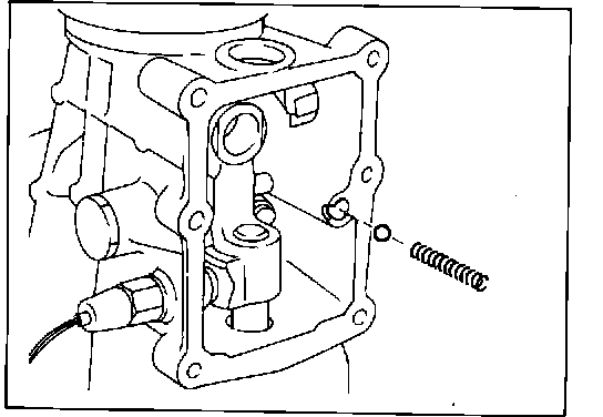
3. Remove the return spring and check ball from the control housing.
4. THIS STEP IS FOR 2WD VEHICLES ONLY.
Remove the speedometer pinion from the rear extension.
RETAINING PIN:
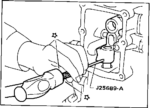
5. Drive out the retaining pin from the striking arm.
6. Remove the ten bolts (14 mm) between the rear extension and transmission case (on 4WD some bolts are 8 mm internal hex).
REAR EXTENSION:
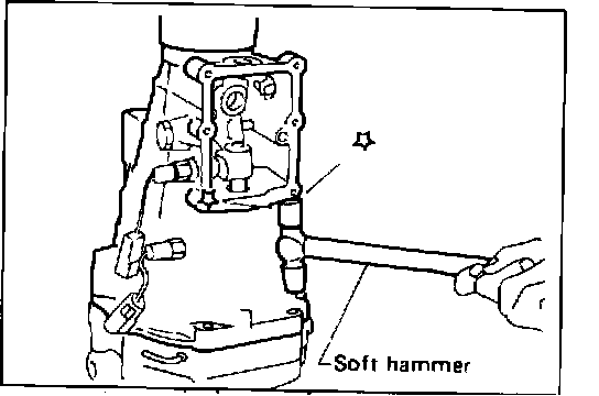
7. Remove the rear extension together with the striking arm by tapping with a soft hammer.
CAUTION: When removing the rear extension, make sure the neutral switch plunger does not fall out.
FRONT COVER:
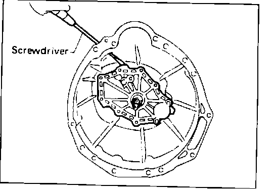
8. Remove the nine bolts (12 mm) on the front cover. Then remove the front cover.
RINGS:
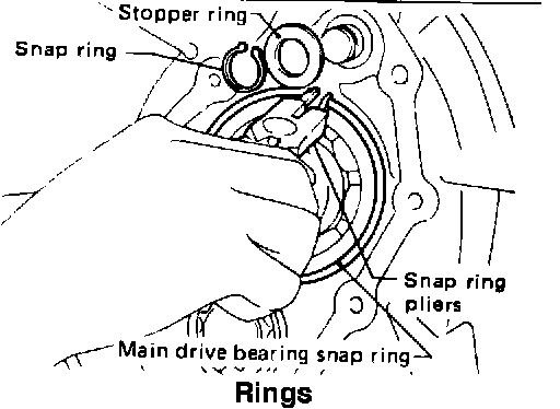
9. Remove the snap ring stopper ring and the front main drive bearing snap ring.
CAUTION: If the snap ring and stopper ring are not removed, the striking lever will be damaged during case removal.
TRANSMISSION CASE:
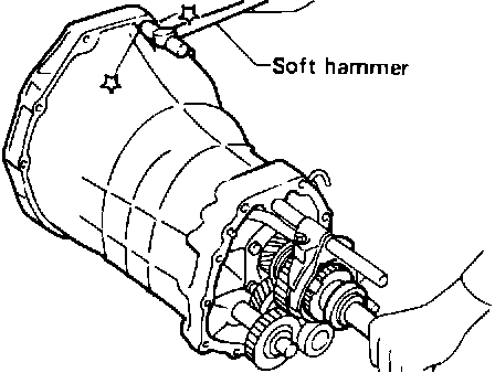
10. Remove transmission case by tapping with a soft hammer.
11. Mount the adapter plate in a vise using soft jaws to protect the adapter plate.
O.D./REVERSE ROD:
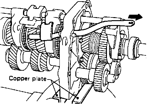
12. Remove the bolt (12 mm) on O.D./REVERSE rod and then remove the rod.
RETAINING PIN:
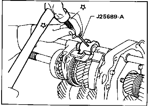
13. Drive out the retaining pin from the striking lever.
CAUTION: The retaining pin must be completely
removed from striking lever and striking rod before moving striking rod, or damage to the striking lever may occur.
STRIKING ROD:
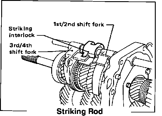
14. Slide out the striking rod enough to free the 1st/2nd shift fork. Install the new 1st/2nd shift fork and slide the striking rod through it, the striking lever, striking interlock and 3rd/4th shift fork.
NOTE DIRECTION of striking interlock. Make sure striking rod moves smoothly.
15. Slide the striking rod the other way to free the reverse shift fork.
REVERSE COUPLING:
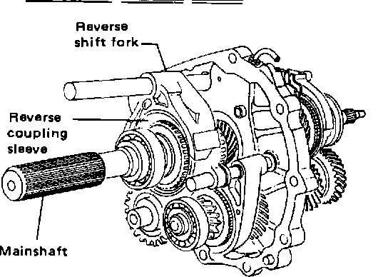
16. Slide the reverse coupling sleeve off the mainshaft.
COUPLING SLEEVE:
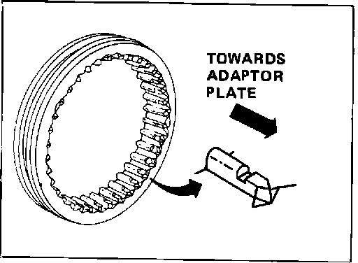
17. Install the new reverse coupling sleeve onto the mainshaft.
CAUTION: Splines on coupling sleeve should point towards the adapter plate.
INSTALLING RETAINING PIN:
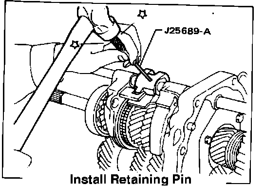
18. Install the new reverse shift fork and slide the striking rod through the hole. Then install a new retaining pin into the striking lever. NOTE DIRECTION of striking interlock. Make sure striking rod moves smoothly.
CAUTION: Use the correct factory retaining pin (2 pins, one inside the other).
19. Install the O.D./reverse fork rod and retaining bolt.
Apply lock sealant to threads of bolt.
ADAPTER PLATE:
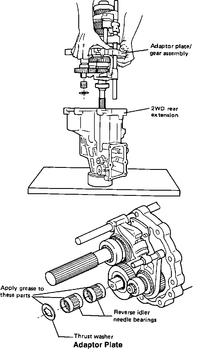
20. Apply Three Bond sealant 1215 or equivalent formed-in-place type gasket/sealant to the rear extension/adapter plate mating surface.
21. Install rear extension to adapter plate/gear assembly.
CAUTION: If the rear extension is stood on end and the adapter plate/gear assembly is installed into it as shown below, apply oil soluble grease to the reverse idler needle bearings and reverse idler rear thrust washer before assembly. This will hold them in place when installing the adapter plate/gear assembly.
RETAINING PIN:
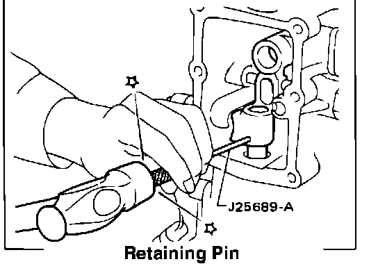
22. Install the original retaining pin into striking arm.
Make sure roll pin head is even with striking lever surface.
23. Apply Three Bond sealant 1215 or equivalent formed-in-place type gasket/sealant to transmission case/adapter plate mating surface.
COUNTER GEAR THRUST BEARING:
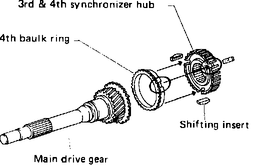
24. Make sure the counter gear thrust bearing is installed. Then make sure all gears are in "neutral".
NOTE: The 4th balk ring should be lined up with the shifting inserts in the 3rd and 4th synchronizer hub.
25. Install transmission case onto adapter plate/gear assembly. Then install the ten attachment bolts.
NEW MOUNTING BOLT:
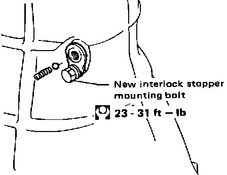
26. Install the interlock stopper with a new mounting bolt included in repair kit. The mounting bolt and check ball plug have a diifferent pitch size and are not interchangeable.
27. Install check ball and check spring into interlock stopper. Use the original short spring (free length: 1.291 in.).
Apply multi-purpose grease to check ball.
ORIGINAL INTERLOCK CHECK BALL PLUG:
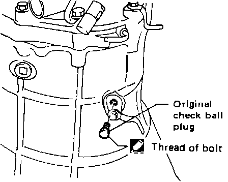
28. Install the original interlock check ball plug.
Apply Three Bond sealant 1215 or equivalent formed-in-place type gasket/sealant to the threads of check ball plug.
SNAP RINGS:
29. THIS STEP IS FOR 2WD VEHICLES ONLY.
Install the speedometer pinion into the rear extension.
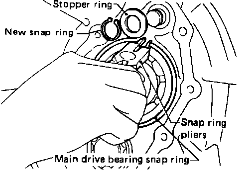
30. Install stopper ring with the new snap ring included in repair kit. Install main drive bearing snap ring.
CAUTION: Make sure snap rings are secure in grooves.
FRONT COVER WITH A NEW GASKET:
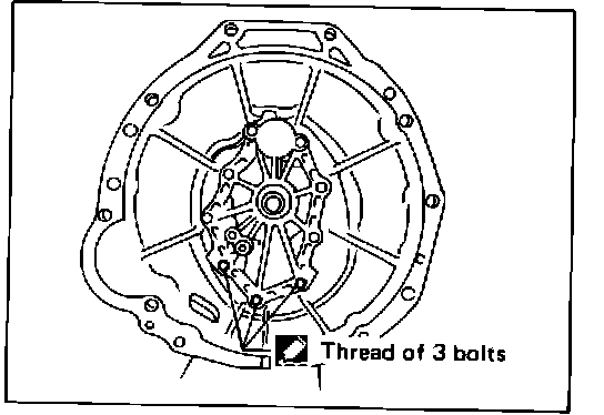
31. Install front cover with a new gasket.
Apply Three Bond sealant 1215 or equivalent formed-in-place type gasket/sealant to the threads of the three bolts indicated below.
CLUTCH RELEASE LEVER:
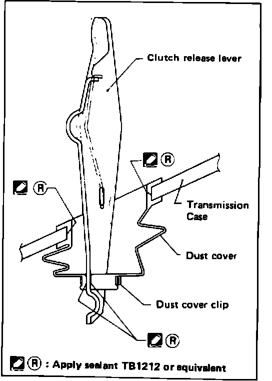
32. Install the clutch release lever.
33. THIS STEP IS FOR 4WD VEHICLES ONLY.
Install the new clutch release lever rubber dust cover using Three Bond sealant 1212 or equivalent RTV silicone type sealant.
SELECT CHECK SPRING:
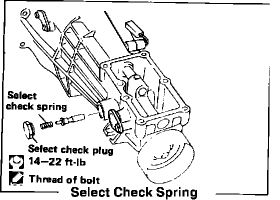
34. Remove the select check plug and select check spring from the left side of the rear extension. Replace the one original check spring with the two new springs (one inside the other) in the kit. Install the check plug.
Apply lock sealant to the threads of select check plug.
RETURN SPRING AND CHECK BALL:
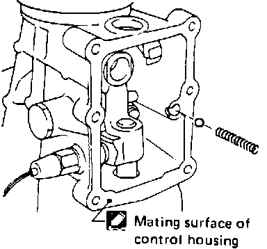
NOTE: Illustration is of 2WD transmission
35. Install the original long return spring and check ball.
Spring Free Length:
2WD Model: 1.866 in. 4WD Model: 1.984 in.