Engine Controls - Knocking Noise When Cold New ECM
88nissan07Classification: Section: Engine Fuel
EF&EC88-016 & Emission Control
Reference:
TECHNICAL BULLETIN TS88-108
Models:
1986.5 Truck (D21)
Date:
August 25, 1988
1986.5 VG30i COLD ENGINE NOISE
APPLIED MODEL: 1986.5 Truck (D21) with VG30i engine
SERVICE INFORMATION
The VG30i engine of some 1986.5 truck vehicles may exhibit a light knocking noise on cold driveaway. This noise can be described as a light knocking or rattling noise that occurs for up to three (3) minutes after cold start-up and is sometimes mistaken as being lifter noise. The knocking noise is most noticeable at 2500-3000 RPM with the engine under load. It is not heard at idle.
This combustion related noise is due to the pre-programmed ignition timing during cold engine operation, and is not harmful to the engine.
New E.C.C.S. control units have been developed to reduce this noise. The countermeasure control units were originally developed for the 1987 model truck, but are applicable to the 1986.5 model truck by using a newly developed sub-harness kit. Part number application and service procedure for the control units and sub-harness kit are as follows.
NOTE: Before installing a new E.C.C.S. control unit, verify that all engine adjustments are set to specification and that there are no other engine noises.
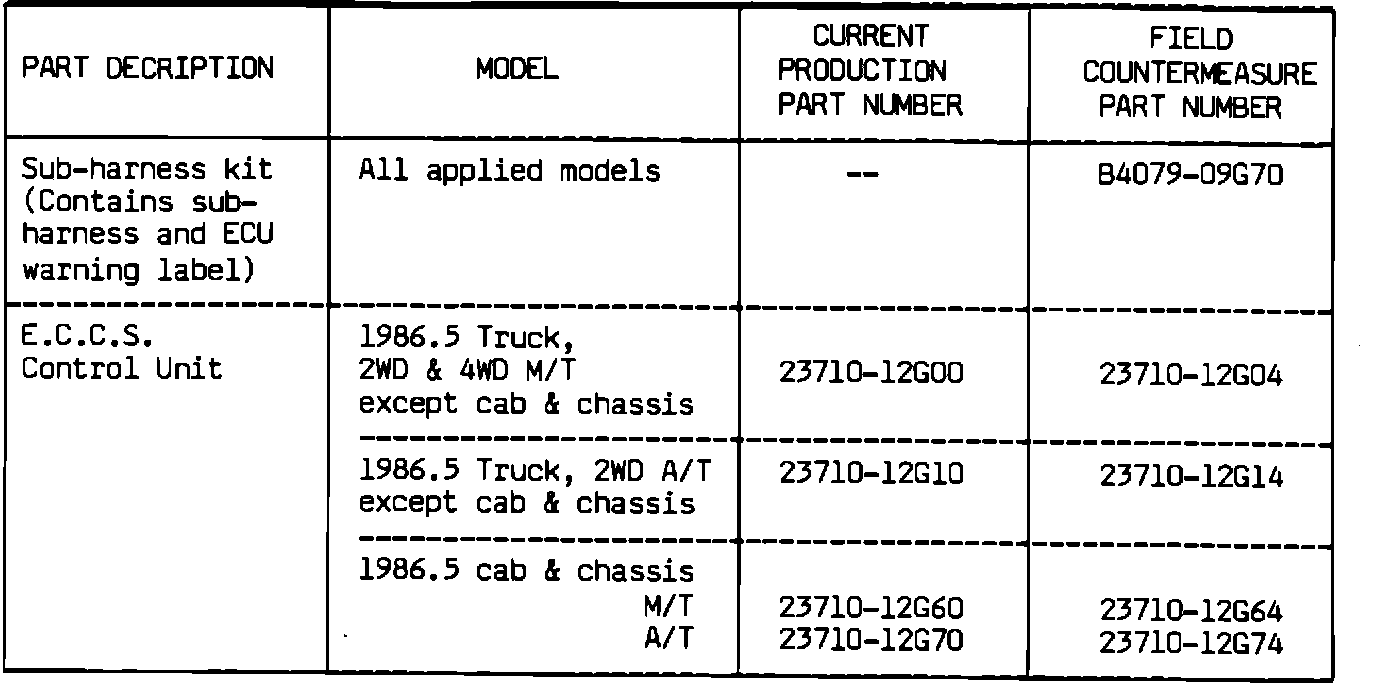
PARTS INFORMATION
SERVICE PROCEDURE
A. Main Relay Connector Modification
1. Disconnect negative battery terminal.
FIGURE 1:
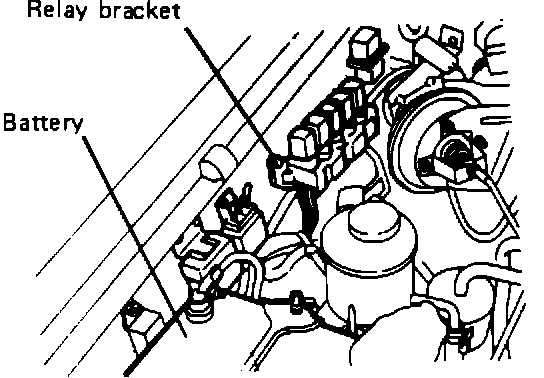
2. Remove relay bracket from right hand hoodledge (Figure 1).
FIGURE 2:
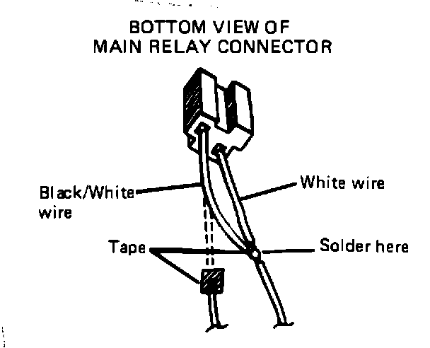
3. From underneath the main relay connector, cut the black/white wire and then splice and solder it to the white wire as shown in Figure 2 below. Cover soldered portion and cut portion of black/white wire with tape.
4. Re-attach relay bracket to right hand hoodledge.
FIGURE 3:
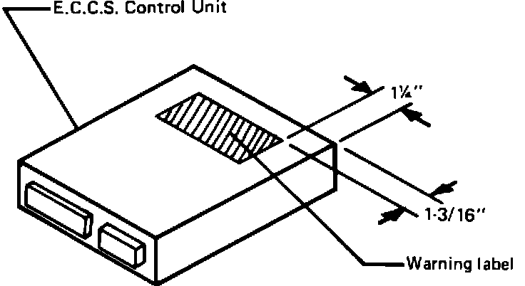
B. Warning Label Application
1. Apply warning label to upper side of countermeasure E.C.C.S. control unit as shown in Figure 3.
FIGURE 4:
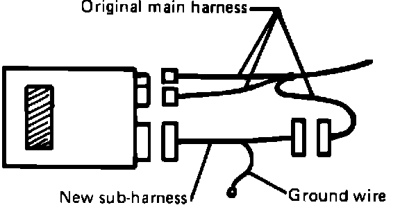
FIGURE 5:
C. E.C.C.S. Control Unit Installation
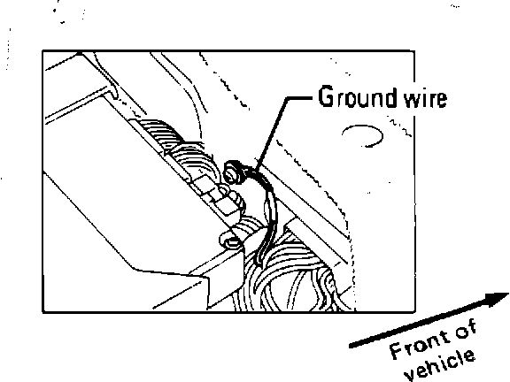
1. When installing the countermeasure E.C.C.S. Control Unit, connect the new sub-harness (15-pin) connector as shown in Figure 4 below. The external wire from this sub-harness must be grounded to the vehicle. Use a self-tapping screw to attach this wire to the raised portion of the floor located forward of the control unit (Figure 5).
NOTE: Make certain that sub-harness wiring is secured and does not interfere with seat operation.
2. The 16- and 20-pin connectors are connected directly to the control unit.
WARRANTY INFORMATION
CS PNC CT Operation No. Flat Rate
4R 22604 99 GB99AA 0.6 Hr.