DTC 55: Pump Motor Locked
- Turn ignition switch to LOCK position. Depress brake pedal at least 40 times or until brake pedal no longer moves. Turn ignition switch to ON position. If pump motor operates, go to step 7
. If pump motor does not operate, go to next step.
- Turn ignition switch to LOCK position. Disconnect Hydraulic Brake Booster (HBB) connector B-17. Measure resistance between Connector B-17 terminal No. 7 (Black wire) and ground. See Fig 1
. If resistance is less then 2 ohms, go to step 4
. If resistance is more than 2 ohms, go to next step.
- Inspect HBB connector B-17 for damaged or corroded terminals. Repair connector and black wire as necessary. Retest system for normal operation. If problem persists, go to next step.
- Disconnect HBB connector B-18. Measure resistance between HBB connector B-18 terminal No. 32 (Black wire) and ground. See Fig 2
. If resistance is less then 2 ohms, go to step 6
. If resistance is more than 2 ohms, go to next step.
- Inspect HBB connector B-18 for corroded or damaged terminals. Repair connector if necessary, then retest system for normal operation. IF connector is okay, repair Black wire between connector B-18 and ground. Retest system for normal operation.
- Remove HBB from vehicle. See HYDRAULIC BRAKE BOOSTER
under REMOVAL & INSTALLATION. Remove pump motor and lead wire from HBB. Apply voltage across pump motor terminals, observe pump motor operation. Check lead wire for continuity. If pump motor and lead wire are okay, replace HBB master cylinder and hydraulic unit. If pump motor is faulty, replace motor and retest system for normal operation.
- Disconnect Hydraulic Brake Booster (HBB) connector B-17. Turn ignition switch to ON position. Measure voltage between HBB connector B-17 terminal No. 4 (Orange wire) and ground. Measure voltage between HBB connector B-17 terminal No. 6 (Light Blue wire) and ground See Fig 1
. If measured voltage is between 4.5 and 5.5 volts, go to next step. If voltage is not between 4.5 and 5.5 at both terminals, go to step 9
.
- Inspect HBB connector B-17 for corroded or damaged terminals. Repair as necessary. If problem persists, replace HBB master cylinder and hydraulic unit assembly. See HYDRAULIC BRAKE BOOSTER
under REMOVAL & INSTALLATION. Retest system for normal operation.
- Disconnect HBB connector B-17 and ABS-ECU connector E-106 for damaged or corroded terminals. See Figure
If connectors are okay, go to next step. If connectors are damaged, repair as necessary retest system for normal operation.
- Check Pink, Orange and Light Blue wires between HBB connector B-17 and ABS-ECU connector E-106. See WIRING DIAGRAMS
. Repair wiring as necessary, then retest system for normal operation. If wiring is okay and problem persists, replace ABS-ECU. See ABS ELECTRONIC CONTROL UNIT
under REMOVAL & INSTALLATION in ANTI-LOCK - MONTERO article. Retest system for normal operation.
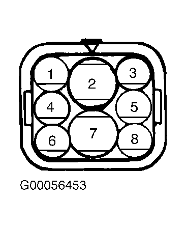 Courtesy of MITSUBISHI MOTOR SALES OF AMERICA.
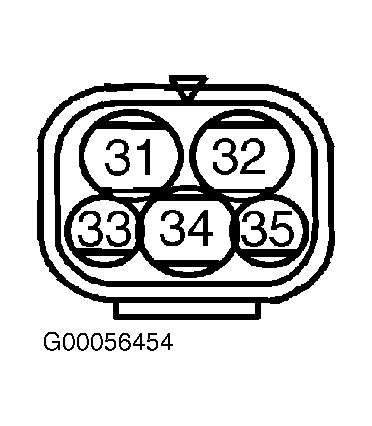 Courtesy of MITSUBISHI MOTOR SALES OF AMERICA.