DTC 17 & 18: Ignition Switch Circuit Open
- If DTC 17 was recorded, go to next step. If DTC 18 was recorded, go to step 5
.
- Turn ignition switch to LOCK position. Disconnect ABS-ECU 26 pin connector E-105. Turn ignition switch to START position. Measure voltage between ABS-ECU connector E-105 terminal No. 13 (Red/Yellow wire) and ground. See Fig 1
. If battery voltage is present, replace ABS-ECU. See ABS ELECTRONIC CONTROL UNIT
under REMOVAL & INSTALLATION in ANTI-LOCK - MONTERO article. If battery voltage is not present, go to next step.
- Inspect ABS ECU connector E-105 for damaged or corroded terminals, repair if necessary. Retest system for normal operation. If connector is okay, go to next step.
- Check Red/Yellow wire between ABS ECU and junction block D-212 (located underneath steering wheel). Inspect Fuse No. 5 (10 amp) at junction block D-212. Repair wiring or replace fuse as necessary. Check Blue/Red wire between ignition switch and junction block D-212, repair wire as necessary. See WIRING DIAGRAMS
. If wiring and Fuse are okay, retest system for normal operation.
- Turn ignition switch to LOCK position. Disconnect ABS-ECU pin connector E-106. See Fig 2
. Turn ignition switch to START position. Measure voltage between ABS-ECU connector E-106 terminal No. 31 (Orange/Green wire) and ground. If battery voltage is present, replace ABS-ECU. See ABS ELECTRONIC CONTROL UNIT
under REMOVAL & INSTALLATION in ANTI-LOCK - MONTERO article. If battery voltage is not present, go to next step.
- Check ABS-ECU harness connector E-106 for damaged or corroded terminals, repair if necessary. Retest system for normal operation. If connector is okay, go to next step.
- Check Green/Orange wire between ABS-ECU connector E-106 and dedicated fuse No. 24 (10 amp). See WIRING DIAGRAMS
. Repair wiring as necessary. Inspect fuse No. 24, replace if necessary. Inspect Blue/Red wiring between ignition switch and dedicated fuse No. 24. Repair wiring as necessary. Retest system for normal operation.
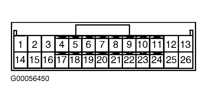 Courtesy of MITSUBISHI MOTOR SALES OF AMERICA.
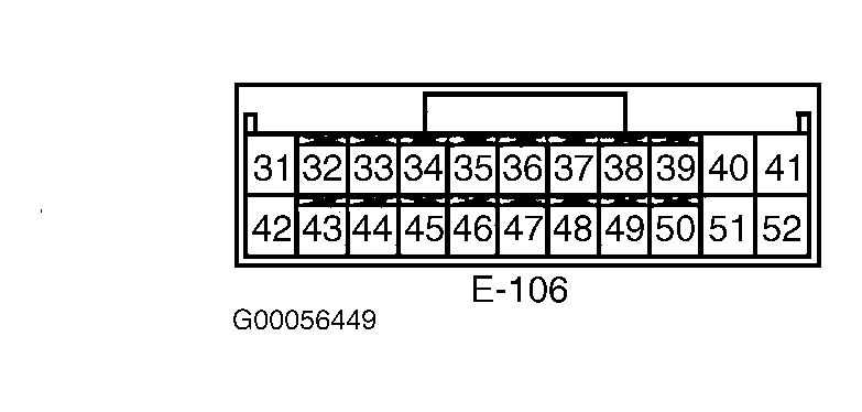 Courtesy of MITSUBISHI MOTOR SALES OF AMERICA.