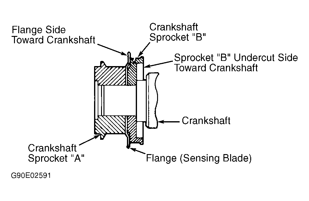
- Install rear timing belt covers, engine support bracket and crankshaft key. Install crankshaft sprocket "B" so undercut side is toward crankshaft. See Fig 1.
 Courtesy of MITSUBISHI MOTOR SALES OF AMERICA.
CAUTION:
Ensure right silent shaft spacer is installed with chamfered side toward oil seal, or damage to oil seal will result.
- Coat outer diameter of right silent shaft spacer with engine oil. Install spacer with chamfered side toward oil seal. Install right silent shaft sprocket.
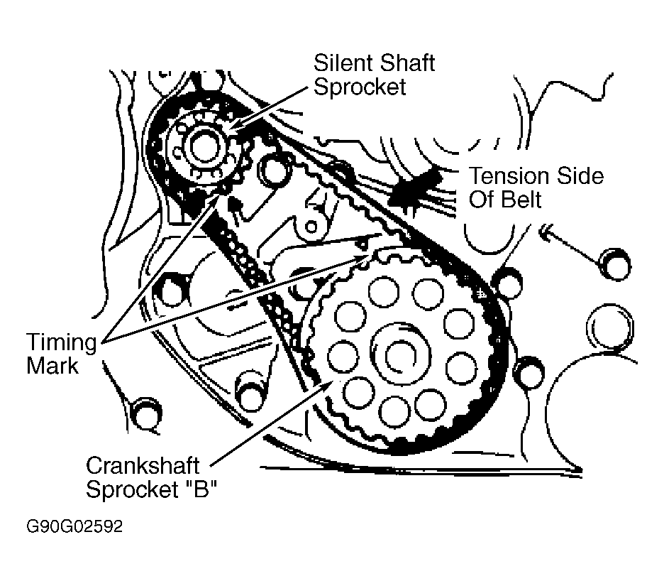
- Align crankshaft sprocket "B" and right silent shaft timing marks. See Fig 2. Install timing belt "B" on sprockets. Ensure belt is installed in original direction of rotation and no slack exists in belt.
 Courtesy of MITSUBISHI MOTOR SALES OF AMERICA.
CAUTION:
When tightening bolt, ensure tensioner does not rotate, or excessive pressure will be applied to timing belt.
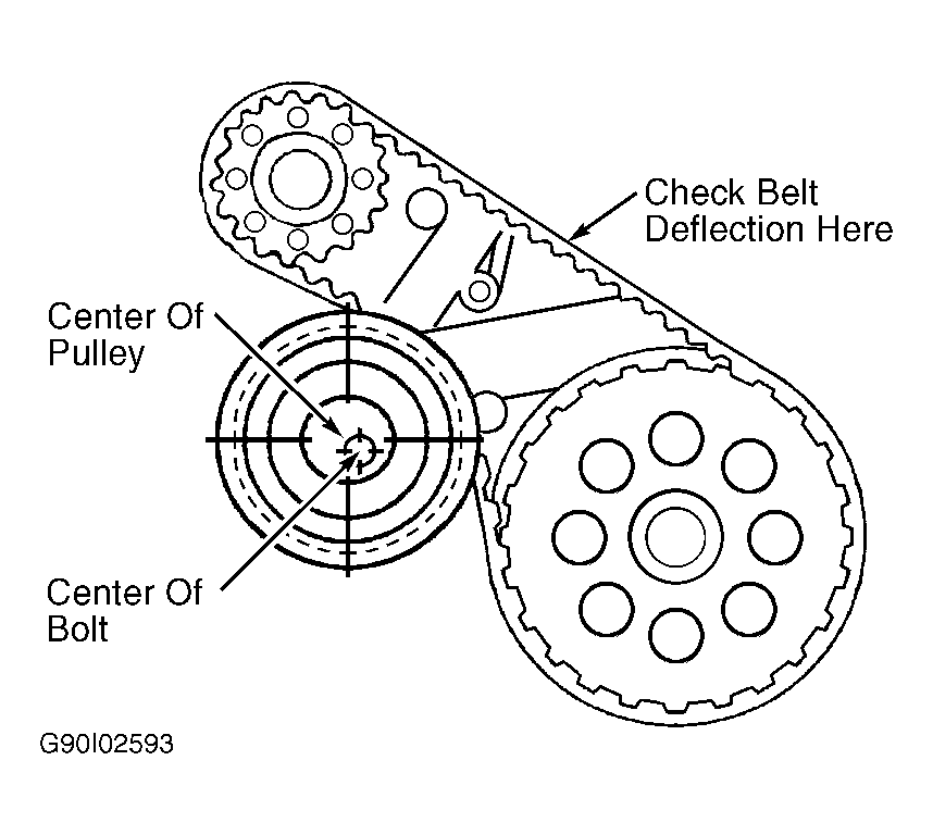
- Install timing belt tensioner "B" so center of pulley is located left of tensioner bolt. See Fig 3. Ensure flange on tensioner pulley is toward front of engine. Rotate tensioner inward toward timing belt until belt is tight. Tighten tensioner bolt.
- Check belt deflection at designated area. See Fig 3. Belt deflection should be .20-.28" (5.0-7.1 mm). Readjust timing belt if belt deflection is not within specification.
 Courtesy of MITSUBISHI MOTOR SALES OF AMERICA.
- Install flange in front of crankshaft sprocket "B", with offset toward crankshaft. See Fig 1. Install crankshaft sprocket "A". Install camshaft and oil pump sprockets. Tighten bolts to specification. See TORQUE SPECIFICATIONS at end of article.
- Install tensioner spring, tensioner spacer and timing belt "A" tensioner. Ensure upper end of tensioner spring contacts water pump. Rotate tensioner toward water pump, and temporarily tighten nut.
- Ensure all timing marks are aligned. See Figure. When aligning oil pump sprocket timing marks, remove plug from cylinder block. See Figure. Insert a .31" (8.0 mm) diameter Phillips screwdriver into plug hole.
- If screwdriver can only be inserted .79-.98" (20.0-24.9 mm), rotate oil pump sprocket one revolution, and realign timing mark. Insert screwdriver, and ensure it can be inserted at least 2.36" (59.9 mm). DO NOT
remove screwdriver until timing belt is installed.
- Install timing belt "A" on sprockets. Ensure no slack exists on tension side of belt. See Figure. Install timing belt on crankshaft sprocket "A", then on oil pump sprocket and then on camshaft sprocket. If reused, ensure belt is installed in original direction of rotation.
- Loosen tensioner nut to allow spring tension to be applied to timing belt. Ensure all timing marks are aligned. Remove screwdriver and install plug.
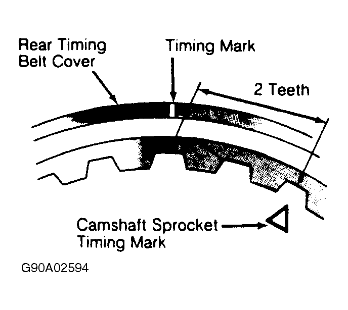
- To apply tension on timing belt, rotate crankshaft clockwise so camshaft sprocket moves 2 teeth past timing mark on rear timing belt cover. See Fig 4. DO NOT
rotate crankshaft counterclockwise.
 Courtesy of MITSUBISHI MOTOR SALES OF AMERICA.
CAUTION:
DO NOT
tighten tensioner spacer nut before tightening tensioner bolt, or timing belt tensioner will rotate and apply excessive pressure on timing belt.
- Rotate tensioner inward toward timing belt. Ensure timing belt fully engages camshaft sprocket. Tighten timing belt tensioner bolt. Tighten tensioner spacer nut.
- At midway location between camshaft sprocket and oil pump sprocket, push timing belt "A" outward toward lower timing belt cover. Note clearance between timing belt and cover. See Fig 5. Clearance should be .47" (12.0 mm). Timing belt may need to be readjusted.
- To complete installation, reverse removal procedure. Ensure proper length bolts are installed in designated areas in timing belt covers. See Fig 6.