Malfunction In Actuator Circuit
- Determine malfunctioning actuator circuit according to output diagnostic trouble code. See TROUBLE CODE ACTUATOR IDENTIFICATION table. Using Multi-Use Tester (MUT), force drive actuator on malfunctioning circuit to SOFT, MEDIUM and HARD settings. Refer to MUT manufacturer's instructions.
- With vehicle stationary, actuator service data indication on MUT should correspond with force-driven setting from MUT. If actuator service data indications test as specified, actuator is okay. If actuator service data indications do not test as specified, go to next step.
- Remove cap from top of shock absorber associated with diagnostic trouble code. See TROUBLE CODE ACTUATOR IDENTIFICATION table. Disconnect appropriate actuator harness connector. Turn ignition on.
- Measure voltage between ground and actuator harness connector terminals No. 1 and 3. See Fig 1. Ensure voltage at each terminal is 5 volts. If specified voltage is not present at any terminal, go to next step. If specified voltage is present at each terminal, go to step 6).
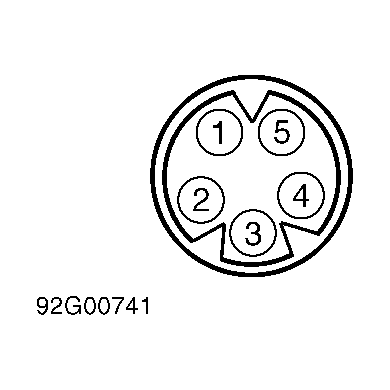 Courtesy of MITSUBISHI MOTOR SALES OF AMERICA.
- Turn ignition off. Check defective circuit(s) between actuator harness connector terminal No. 1 and/or 3 and appropriate ECS control unit harness connector terminal. See ECS-TO-ACTUATOR CIRCUIT TERMINAL IDENTIFICATION table. Repair harness as necessary. If harness is okay, replace ECS control unit.
- Using an ohmmeter, check for continuity between ground and actuator harness connector terminals No. 2 and 4 (Black wires). See Fig 1. If continuity is present at both terminals, go to next step. If continuity is not present at either terminal, repair appropriate circuit.
- Turn ignition on. Using MUT, force drive appropriate actuator while measuring voltage between ground and actuator harness connector terminal No. 5. See Fig 1. Refer to MUT manufacturer's instructions for specific procedure.
- Voltage should be zero volts normally and jump to 9 volts during forced activation (drive) of actuator. If actuator does not test as specified, go to next step. If actuator tests as specified, go to step 10).
- Turn ignition off. Check continuity between appropriate actuator harness connector terminal No. 5 and appropriate ECS control unit harness connector terminal. See ECS-TO-ACTUATOR CIRCUIT TERMINAL IDENTIFICATION table. Repair harness as necessary. If harness is okay, replace ECS control unit.
- Replace malfunctioning shock absorber assembly (and actuator) with a known good unit. Recheck for self-diagnostic trouble codes. If original trouble code is reset, replace ECS control unit. If original trouble code is not reset, replace shock absorber assembly.
TROUBLE CODE ACTUATOR IDENTIFICATION
| Trouble Code |
Related Actuator Circuit |
| 61 |
Right Front |
| 62 |
Left Front |
| 63 |
Right Rear |
| 64 |
Left Rear |
ECS-TO-ACTUATOR CIRCUIT TERMINAL IDENTIFICATION
| Actuator Connector Terminal No. |
CS Control Unit Connector Terminal No. |
| Front Right Actuator |
| 1 |
7 |
| 3 |
6 |
| 5 |
5 |
| Front Left Actuator |
| 1 |
10 |
| 3 |
9 |
| 5 |
8 |
| Rear Right Actuator |
| 1 |
3 |
| 3 |
2 |
| 5 |
11 |
| Rear Left Actuator |
| 1 |
16 |
| 3 |
15 |
| 5 |
14 |